
| Product ID | Model | System | Length |
|---|---|---|---|
| FT5XLp | BTPL | F5+, F5 | 24" |
| FT5Lp | BTPL | F5+, F5 | 19" |
| FT5p | BTP | F5+, F5 | 15" |
| FTR5Lp | BTPL | F5+, F5 | 19" |
| FTR5p | BTP | F5+, F5 | 15" |
| FTR5s | BTS | F5+, F5 | 8" |
| FT5XS | BTM | F5+, F5 | 6" |
| FT2L+ | BTWL | F2+, F5+ | 19" |
| FT2 | BTW | F2+, F2 F5+, F5 | 15" |
| FT2S | BTS | F2+, F2 F5+, F5 | 8" |
| FT2XS | BTM | F2+, F2 | 6" |
| FT1 | BTW | F1 | 15" |
| FT1S | BTS | F1 | 8" |
| FT1XS | BTM | F1 | 6" |
DigiTrak® Falcon® F5+ User Manual
DCI DigiGuide 2026.03.13
DCI DigiGuide User Manual
2026.03.13- Only operate your DCI guidance system in accordance with the operating instructions for your system.
- Serious injury and death, as well as property damage, can result if underground drilling equipment strikes a natural gas line, high-voltage electrical cable, or other utility.
- Work slowdowns and cost overruns can occur if you do not use your system correctly.
- Properly calibrate your DCI guidance system anytime you change frequencies, transmitters, or drill heads and validate the calibration before every drilling project. If you fail to do so, depth readings will likely be inaccurate.
- Interference can lead to inaccurate depth readings and/or interruption of data. See "Special Notes About Interference" for more details.
- DCI guidance systems are used to locate and guide the transmitter (housing) underground. They cannot be used to locate underground utilities.
- Failure to find the front and rear locate points can lead to inaccuracies which may result in drilling off-path and striking an underground utility.
- The locate line on a DCI locator does not indicate the position of the drill head. DCI locators track the transmitter in its housing, which sits behind the drill bit. Also, when drilling steep and/or deep, the locate line may indicate a position behind or ahead of the transmitter. Please see "Steep and Deep" under Advanced Topics for important information about accurately locating the drill head when drilling steep and/or deep.
- Ensure that all underground utilities have been located, exposed, and/or accurately marked prior to drilling. Follow all proper safety precautions, such as potholing.
- DCI equipment is not explosion-proof and should never be used near flammable or explosive substances.
- Wear jobsite protective/safety clothing such as dielectric boots, gloves, hard hat, high-visibility vest, and safety glasses.
- Install transmitters into the drill housing as soon as possible after powering on. If you can't, unscrew the cap to power off the transmitter until you can install the transmitter into the drill housing to reduce RF exposure.
- Comply with federal, state, and local governmental regulations (such as OSHA) and all other customary or required safety precautions.
If you have any questions about the operation of your guidance system, please contact DCI Customer Service for assistance.
While DCI guidance systems provide you with technology to combat active interference (and passive interference, with the Sub-K Rebar transmitter), no guidance system is immune to all interference.
Interference can lead to inaccurate depth readings and/or interruption or loss of data. Never rely on data that does not display quickly and/or remain stable.
The Falcon frequency optimizer selects frequencies based on measured interference at a specific time and location.
Interference levels change with time and with even minor changes in location. The frequency optimizer is not a substitute for prudent operator judgment. If performance drops while drilling, consider switching to the other selected band (not available on the Falcon F1) or use Max Mode.
An A on the screen can indicate signal Attenuation due to the presence of excessive interference, which can make depth readings inaccurate. Attenuation is normal in shallow depths less than 8 ft (2.4 m). If the signal strength is also flashing; this indicates extreme interference. Depth and locate points may be compromised and the locator will not calibrate.
Interference is classified as either active (generating electro-magnetic signals) or passive (material that can conduct or block electro-magnetic signals). Sources of interference may include:
Active
- Traffic signal loops
- Buried dog fences
- Cathodic protection
- Radio communications
- Security systems
- Microwave towers
- Power, phone, fiber-trace and cable TV lines
Passive
- Metal pipes
- Rebar
- Trench plates
- Chain-link fences
- Vehicles
- Saltwater/salt domes
- Conductive earth, such as iron ore
If you have any questions about the operation of your guidance system, please contact DCI Customer Service for assistance.
System working altitude: up to 6562 ft (2000m).
Storage and transportation temperature: -40° to 149°F (-40° to 65°C).
Operation may be compromised if the equipment is subjected to conditions outside these specified limits.
Ship in original carrying case or packaging of sufficient durability to prevent mechanical shock to equipment during transportation.
If you have any questions about the operation of your guidance system, please contact DCI Customer Service for assistance.
Remove the batteries from all system components during shipping and prolonged storage. Failure to do so may result in battery leakage, which may lead to risk of explosion, health risks, and/or damage.
Store and transport batteries using a suitable protective case that will keep batteries safely isolated from one another. Failure to do so may result in short circuits, which may lead to hazardous conditions including fire.
Lithium-ion batteries must be packaged and shipped by trained and certified personnel only. Never ship damaged batteries.
If you have any questions about the operation of your guidance system, please contact DCI Customer Service for assistance. Connect to DCI Customer Service with the Contact link in the DigiGuide App or find a list of offices in the back of any printed DigiGuide manual and on the DCI website: digital-control.com.
If you plan to store the battery packs for any period of time, please follow these guidelines:
Store and transport batteries using a suitable protective case that will keep batteries safely isolated from one another. Failure to do so may result in short circuits which may lead to hazardous conditions including fire.
Do not store the battery pack at temperatures greater than 113° F (45°C).
Do not store the battery pack in a fully discharged state.
Do not store the battery pack in the battery charger.
Do not store multiple batteries together where their terminals or other loose conductive materials may contact one another and cause a short circuit.
Never ship damaged batteries.
If a lithium-ion battery pack will be stored for an extended period of time, pre-charge the battery to a charge level of 30% to 50% (two or three LEDs illuminated on the meter).
Do not store the battery pack for more than one year unless it is periodically recharged to the 30% to 50% level.
Lithium batteries are regulated by UN3480 and UN3481 lithium-ion batteries.
Lithium batteries are considered Class 9 Miscellaneous Dangerous Goods under International Air Transportation Association (IATA) regulations; IATA regulation and Ground Transportation regulations 49 CFR 172 and 174 apply. These batteries must be packaged and shipped by trained and certified personnel only. Never ship damaged batteries.
This symbol on equipment indicates that the equipment must not be disposed of with your other household waste.
Instead, it is your responsibility to dispose of such equipment at a designated collection point for the recycling of batteries or electrical and electronic equipment. If the equipment contains a banned substance, the label will show the pollutant (Cd = Cadmium; Hg = Mercury; Pb = Lead) near this symbol.
Before recycling, ensure batteries are discharged or the terminals are covered with adhesive tape to prevent shorting.
The separate collection and recycling of your waste equipment at the time of disposal will help conserve natural resources and ensure it is recycled in a manner that protects human health and the environment.
For more information about where you can drop off your waste equipment for recycling, please contact your local city office, your household waste disposal service, or the shop where you purchased the equipment.
U.S.: Contact The Battery Network’s Drop-off Locator at 1-877-2-RECYCLE or visit www.batterynetwork.org.
Ce symbole figurant sur l'équipement indique qu'il ne faut pas le jeter avec les ordures ménagères.
Il vous incombe en effet d'éliminer ce type d'équipement en l'amenant à un site de récupération désigné pour le recyclage des batteries/piles ou d'appareils électriques et électroniques. Si le matériel contient une substance interdite, l'étiquette indiquera le polluant (Cd = cadmium ; Hg = mercure ; Pb = plomb) à côté de ce symbole. Avant de recycler les batteries, assurez-vous qu'elles sont déchargées ou que les bornes sont recouvertes d'un ruban adhésif pour éviter les courts-circuits. La collecte séparée et le recyclage de votre matériel usagé au moment de l'élimination permettront de conserver les ressources naturelles et de veiller à un recyclage en bonne et due forme, qui protège la santé humaine et l'environnement. Pour plus d'informations sur les sites où vous pouvez déposer votre matériel usagé à recycler, veuillez contacter les autorités municipales, votre service d'élimination des déchets ménagers ou le lieu d'achat du matériel.
Locating in the horizontal directional drilling (HDD) industry was initially based on locating a buried cable by sweeping the locator back and forth to find the highest signal strength (peak signal), indicating that the locator was over the cable. Unfortunately, this method did not always guarantee an accurate location of the cable, nor did it provide any depth information.
This “peak signal” method was adapted to HDD with the introduction of a transmitter that provides information on the position and depth of the drill head. However, this method is unreliable and inaccurate because the peak signal strength is not always directly above the transmitter housing.
In addition, peak signal locating doesn’t show where the drill tool is headed. Think of drilling like driving a car: it is more effective to look ahead through the windshield to see where you are going than to look down at the road through the floorboard to keep the car (drill tool) on the road (drill path).
DigiTrak locators are part of the integrated Digital Guidance System. The system comes standard with a locator, a remote display, a transmitter, batteries, and a battery charger.
You can purchase additional transmitters, batteries, chargers, and the R1 terrain mapper from your local dealer.
You can find a chart of the compatible transmitters in the "Compatible Transmitters" article of the DCI DigiGuide App.
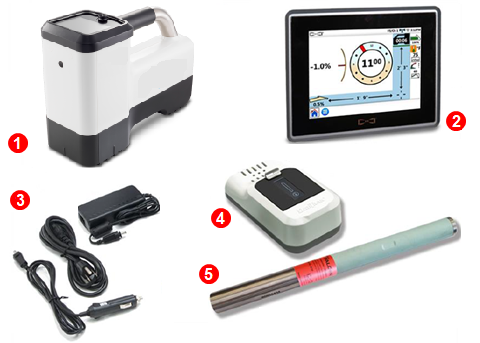
1. Locator - The locator displays and interprets the information received from the transmitter in the drill housing.
2. Remote Display - A freestanding or drill-mounted, color touchscreen that displays the locator information and rod-by-rod drill information. A core suite of apps is included: LWD Live, Target Steering, Strip Chart, and Frequency Change.
3. Battery cables
4. Locator battery and charger
5. Transmitter - A transmitter generates a magnetic field detected by the Falcon locator. The transmitter must be paired and calibrated to the locator prior to use. The technical specifications in the DCI DigiGuide App list the compatible batteries for each model.
The manuals for the locators and Aurora display are available in the DCI DigiGuide App. Transmitter articles are included in the individual locator manuals in the Advanced chapters.
DCI’s design uses a “locate point” in the transmitter signal. The Front Locate Point (FLP), which is out ahead of the transmitter, shows where the transmitter housing is heading.
DCI invented the Ball-in-the-Box user interface to make it quick and intuitive to find a locate point, speeding up drilling jobs: just move the locator so the ball moves into the box on the screen.

Finding a locate point also helps you find the drill head itself.
There is a second locate point behind the transmitter called the Rear Locate Point (RLP). The two locate points, combined with a Locate Line (LL), pinpoint the precise location of the transmitter housing below ground.
They are arranged like an airplane, where the Front Locate Point is the plane’s nose, the Rear Locate Point is the tail, and the Locate Line is the wings.

If your drill path requires a consistent depth or to maintain a constant pitch, use the predicted depth feature at the Front Locate Point. This eliminates the need for depth readings over the transmitter, speeding up the drilling process.
Interference can cause incorrect locate data that reduces locating accuracy. There are two different types of interference that can distort the transmitter signal: active and passive.
Active interference, or “noise”, consists of anything that emits a signal that interferes with the transmitter signal. Example sources include power lines, radio towers, cathodic protection, fiber tracer lines, invisible dog fences, security systems, and traffic signal loops. Falcon’s frequency optimizer finds the best frequencies to avoid noise.
Passive interference consists of anything that blocks or distorts the transmitter signal resulting in incorrect depths or missing data. Example sources include rebar, guard rails, bridge abutments, chain link fencing, salt/saltwater, and soil high in metal ore. The Falcon sub-kHz transmitter (available for Falcon F5 and F5+ only) helps cut through passive interference without distorting the signal.
An A on the screen can indicate signal Attenuation due to the presence of excessive interference, which can make depth readings inaccurate. Attenuation is normal in shallow depths less than 8 feet (2.4 m). If the signal strength is also flashing, this indicates extreme interference. Depth and locate points may be compromised and the locator will not calibrate.
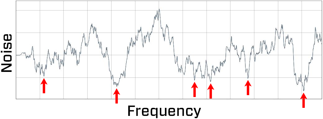
Noise varies by amount and frequency depending on where you are and even the time of day. That’s why it’s important to find the best frequencies for every bore.
This is called frequency optimization, and only Falcon has it. Using frequencies with the highest probability of success against noise increases locating accuracy and reduces the risk of tripping out.
Falcon’s frequency optimizer scans through hundreds of frequencies, then bundles those with the lowest noise into finely-tuned bands that work best for the current job.
Select two bands and switch between them mid-bore if needed (not available on the Falcon F1 with singleband).
The Falcon Plus locators with Quick Scan Pair offer features to make the selection of bands faster and easier. Two clicks select the two preset bands selected for your region.
Falcon F Plus line of locators has a toggle switch on top and a trigger switch under the handle to navigate the menu system and select options.
Use the 4-way toggle switch to access a menu, move between menu options, and open shortcuts.
Shortcuts require you to hold the toggle for a second or longer; we call this a “hold toggle”. For example, from the Locate Mode screen, open a transmitter band selection shortcut by holding the toggle right.
Use the trigger switch to power on the locator, select a menu option, and to take a depth reading.
Pull and release (click) the trigger to select. In some cases, you’ll need to hold the trigger for a second or more to use a function, such as turning the locator on or taking a depth reading.
Utilities increasingly require a digital as-built report to ensure drilling parameters were met.
The DataLog® feature on your locator lets you easily capture and store the rod-by-rod data of your pilot bore.
When used with DCI’s DigTrak LWD app, geo-tagging the entry and exit automatically ties the as-built to a physical location.
With a DigiTrak LWD subscription, use your mobile device to upload DataLogs to your cloud account even during drilling to show progress to back-office personnel.
After importing your DataLog job into our Log-While-Drilling (LWD) software, you can edit, annotate, and finalize the precise report you or your customer requires.
On the DigiTrak Aurora remote display, use our free LWD Live app to view the drill profile in real-time as each rod is completed.
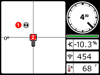
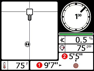
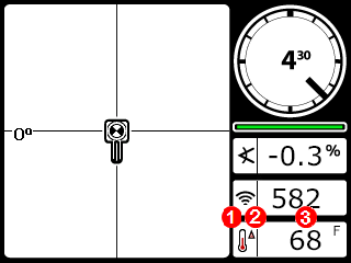
The Locate Mode, Depth, and Predicted Depth screens are the primary screens you will use for locating.
When the locator is detecting a signal from a transmitter, the Locate Mode screen provides real-time data about the transmitter’s location, temperature, pitch, roll, and signal strength.
Depth data appears when the trigger is held at the Locate Line (LL) and predicted depth appears when held at the Front Locate Point.
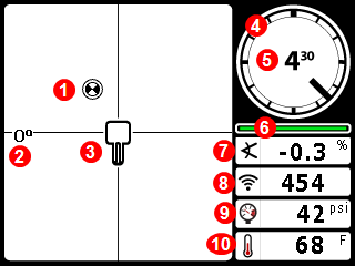
- Locating ball (FLP or RLP)
- Yaw indicator
- Locator
- Roll indicator
- Roll value
- Roll/pitch update meter
- Transmitter pitch
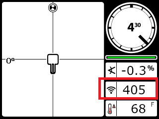
- Power Mode and Transmitter signal strength
- Transmitter fluid pressure
- Transmitter temperature
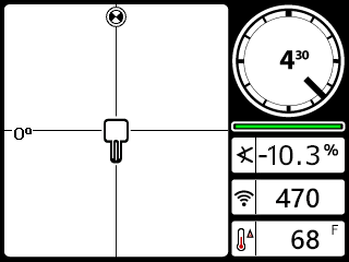
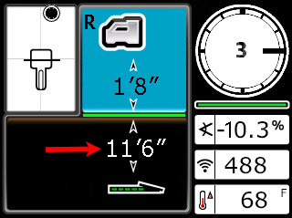
The Depth screen displays when the trigger is held with the locator at the Locate Line (LL).
- Locate point (front or rear)
- Bird's-eye view
- Locate Line (LL)
- Height-Above-Ground (HAG) setting on
- Ground level
- Transmitter depth
- Transmitter battery strength
- Transmitter power level
When the HAG setting is disabled, the locator displays at ground level and must be placed on the ground during depth readings.
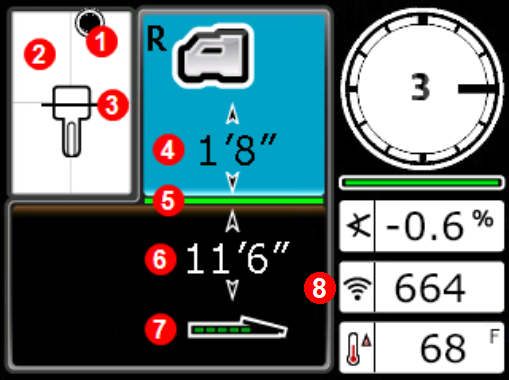
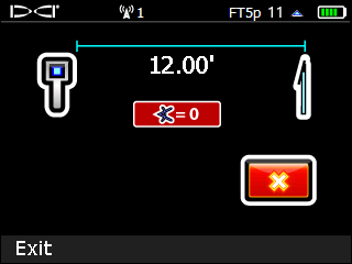
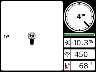
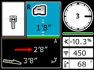
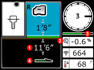
The Predicted Depth screen displays when the trigger is held with the locator at the Front Locate Point (FLP).
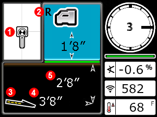
- Ball-in-the-Box at FLP
- Reference Lock * indicator
- Transmitter battery strength and pitch angle
- Horizontal distance between transmitter and FLP
- Predicted depth * of transmitter
The predicted depth is the depth the transmitter is calculated to be at when it reaches the FLP if it continues on its current path.
In this example, if the drill head travels an additional 3'8" (1.12 m) at -0.6% pitch, it will be directly below the locator at 2'8" (0.81 m).
Do not take a predicted depth reading when the locator is over the Rear Locate Point (RLP).
Indicates a reference signal has been obtained for displaying the locate line. Displays at the top of the Locate Mode screen.
The Predicted Depth screen displays when the trigger is held with the locator at the Front Locate Point (FLP). The predicted depth is how deep the transmitter is calculated to be when it reaches the front locate point if it continues on its current path. The predicted depth will also display when the locator is at the Rear Locate Point (RLP), but it will not be correct.
Stuff You Should Know

Registering your equipment activates the product warranty.
Registering also allows us to contact you if it is recovered after being lost or stolen.
If you want to enable the Lock Out Capability (LOC) feature, contact DCI support.
See the DCI website for warranty terms and conditions.
Contact your authorized DCI dealer or DCI to register your equipment.
You will need the equipment serial number and your company contact information.
Here’s where to find your serial number:
- Locator: in the battery compartment
- Transmitter: engraved on the steel body
- Remote display: decal on the back
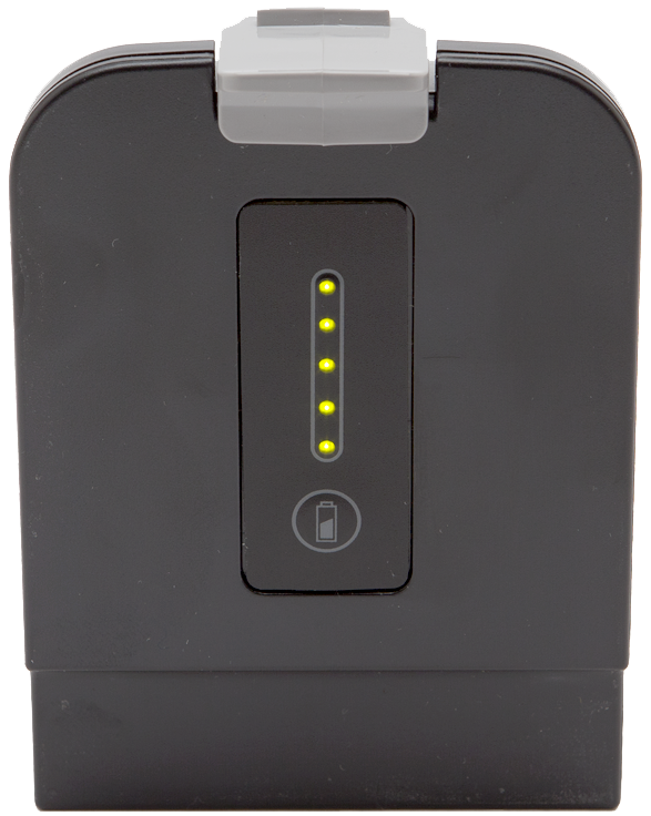
Check the charge level of your locator battery; each of the five lights on a Li-ion battery represents about 20% capacity.
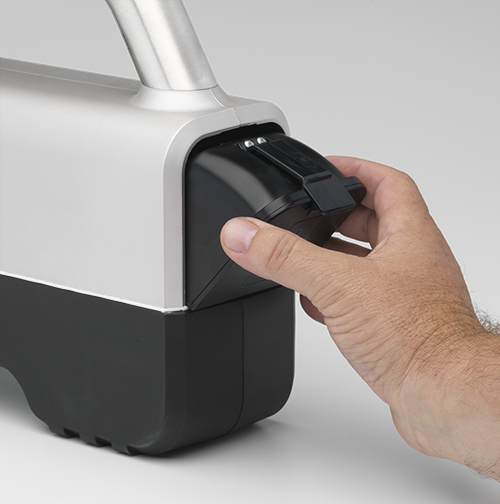
Insert battery in the locator.
Pull the trigger to turn on the locator.
Click to confirm you’ve read the manual.
The regional code for the locator and the transmitter must match. If they don't, contact your DigiTrak dealer.
On the transmitter, look for the globe icon on the etching. The letter or number must match the region code for the locator.
Before You Start
You can change the language of the locator screens. The languages available are:
- English
- 汉语 (Chinese)
- Deutsch (German)
- हिन्दी, हिंदी (Hindi)
- Español (Spanish)
- Русский (Russian)
- Français (French)
- Polski (Polish)*
- Čeština (Czech)*
- Dansk (Danish)*
*These languages are available on locators manufactured after Febuary 2024.
This procedure changes the languages of the screens but does not affect the region. To change the region, contact DCI Customer Support.
From the Main menu, select Settings.
Toggle down to the second page.
Select Language selection.
Select a language. The locator will beep four times and then restart.
Changing the language on the locator does not change the language for remote displays, datalogging reports, apps, or myDCI.
Things you should know
Your locating system can use different transmitters.
The transmitter selected on your locator must match the transmitter in use. See the "List of Compatible Transmitters".
The transmitter and locator must have the same region designation number to communicate with each other and to comply with local operating requirements.
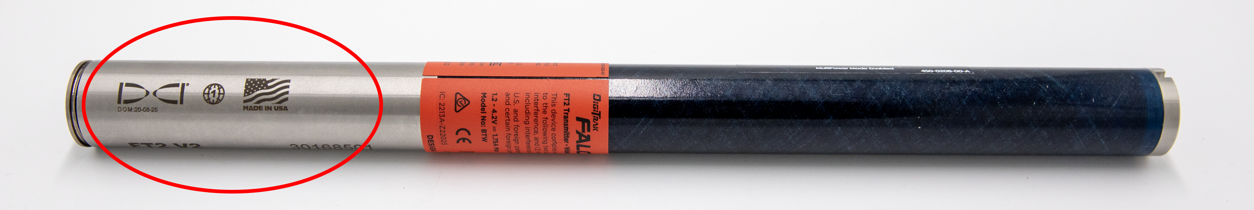
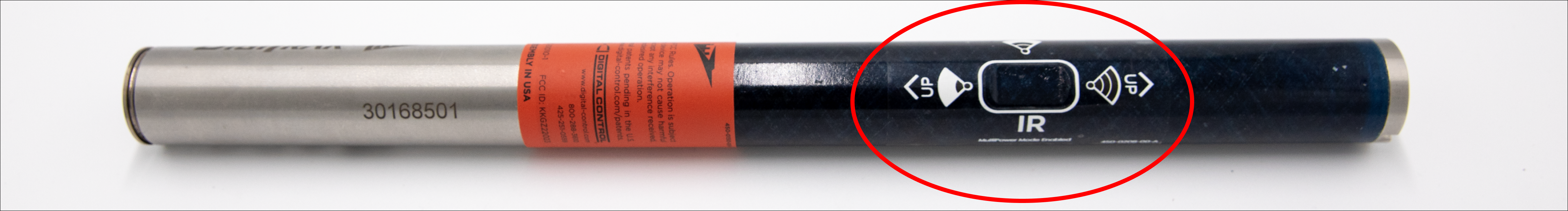
The circle is where you can find the transmitter's region and model number. The region number is inside the globe icon in front of the serial number.
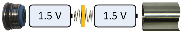
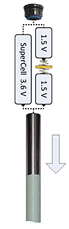
Your transmitter comes with one battery contact spring and one battery cap tool.

Insert batteries positive terminal first. Install one spring between C-cell batteries to help prevent chatter.
If you are using the Falcon Transmitter Adapter (FTA) with a battery, install a Lithium Rechargeable (LiR) battery into the adapter's positive terminal first. For more information on the FTA, see "Falcon Transmitter Adapter for V2 MultiPower "Blue" Transmitters".
Alkaline batteries are not sufficient for High Power Mode. The locator will display a warning.
Do not use a spring with a SuperCell, SuperCell-R, LiR, or FTA.
The transmitter is powered once batteries are inserted and the cap is installed.
Install transmitters into the drill housing as soon as possible after powering on. If you can't, unscrew the cap to power off the transmitter until you can install the transmitter into the drill housing. The transmitter will connect to the locator via Bluetooth while in the housing. Make sure the housing slots are clear of mud and debris, so that the locator can detect the Bluetooth signal from the transmitter.
Stuff You Should Know
Use standard Height-Above-Ground (HAG) to set a height measurement on the locator so you don’t have to put it on the ground for a depth reading.
Raising the locator above the ground also provides separation from underground interference that might otherwise reduce the transmitter’s range or cause variable readings.
If you are using TrakStand HAG, see "Turn on Height Above Ground" in the During Drilling chapter.
HAG must be turned on manually each time after the locator is powered on or calibrated.
To measure for standard HAG, hold the locator at your side as if you were holding a suitcase.
Measure the distance between the ground and the bottom of the locator using a tape measure.
From the Main menu, select HAG.
Select Set HAG.
Target Steering assumes that the locator is on the ground, even if standard HAG is enabled. If TrakStand HAG is enabled, the height set for the Trakstand is adjusted for Target Steering.
Use the keypad to enter the value you measured and select Enter. HAG is now on.
When standard HAG is enabled, the locator must be held at the set height for accurate depth readings.
HAG must be turned on manually each time after the locator is powered on or calibrated.
Check the charge level of your locator battery; each of the five lights on a Li-ion battery represents about 20% capacity.
Insert battery in the locator.
Pull the trigger to turn on the locator.
Click to confirm you’ve read the manual.
The regional code for the locator and the transmitter must match. If they don't, contact your DigiTrak dealer.
On the transmitter, look for the globe icon on the etching. The letter or number must match the region code for the locator.
Stuff You Should Know
Your locating system can use different transmitters.
The transmitter selected on your locator must match the transmitter in use. See the "List of Compatible Transmitters" in the Reference chapter.
The transmitter and locator must have the same region designation number to communicate with each other and to comply with local operating requirements.

These arrows point to the two locations where you can find the transmitter's region and model number. The region number is inside the globe icon in front of the serial number.
Main menu:
If they do not match, use the following process to change the transmitter selection on the locator.
At the Main menu, select Transmitter selection.
Select Transmitter selection (same name, different screen).
Select your transmitter.
A transmitter must be paired and calibrated to the locator before it will provide data.
Before scanning with the Frequency Optimizer (FO) you have three options to select which bands to pair with your transmitter.
Basic - Quick Scan Pair (QSP) – With fewer clicks, bypass the FO to scan and pair the pre-selected Up and Down bands for your region.
Advanced FO - Quick Pick – After scanning, use the two bands with the lowest noise indicated by the FO with white arrows.
Advanced FO - Manual Pick – After scanning, select one or both bands and assign them to up or down.
After using one of the Advanced methods to pick the bands, you will pair them with the transmitter and then calibrate.
Before You Start
Basic - Quick Scan Pair scans noise and selects the best frequencies for the preset Up and Down bands. These presets may not be the best bands for the jobsite.
Use Advanced - Scan Pick Pair to view noise on all bands.
To provide pitch information on your locators, enable full scale sensitive pitch (FSSP), see the article "Enable Full Scale Pitch Resolution" in the Advanced Topics Chapter.
Ensure all transmitters are powered off or more than 100 ft (30.5 m) away from the locator.
Inspect the jobsite and move locator to active noise area of concern or deep part of bore - keep locator above and parallel to bore path.
From the Main menu, select Quick Scan Pair.

Confirm the pre-selected bands and the power levels on the top box on the screen.
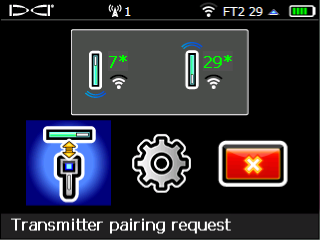
To change the pre-set bands and power levels, click the Quick Scan/Pair option (the gear icon).
If you are using a Sub-k transmitter, QSP assigns a wideband frequency (7, 11, or 16) with Standard power to the Up band and a Sub-k band (0.3, 0.5, or 0.7) with Low power to the Down band.
Insert batter(ies) positive terminal first and install the battery cap to power on the transmitter.
Align the transmitter so its IR port is near and facing the round IR port on the front of the locator.
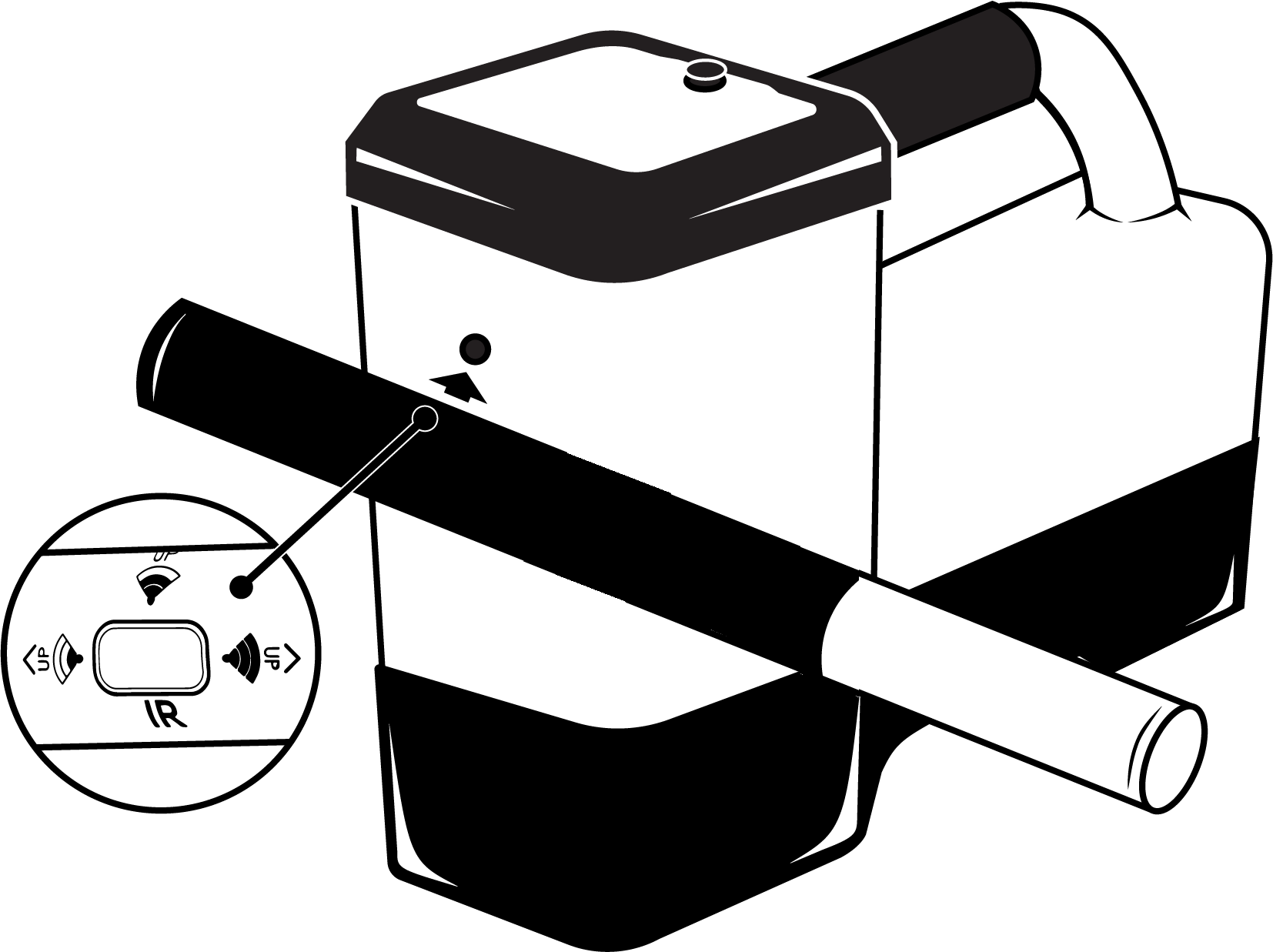
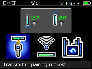
Falcon locators with programmable power mode override any other selection method when used with a V2 transmitter.
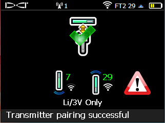
Click Transmitter pairing request.
Confirm the pairing and power mode, and then click to continue to Calibration.
Install transmitters into the drill housing as soon as possible after powering on. If you can't, unscrew the cap to power off the transmitter until you can install the transmitter into the drill housing. The transmitter will connect to the locator via Bluetooth while in the housing. Make sure the housing slots are clear of mud and debris, so that the locator can detect the Bluetooth signal from the transmitter.
Scan Pick Pair allows you to scan the bore path for noise and then select the lowest noise bands identified by the locator or manually.
You may decide to continue to use the currently selected bands or to select bands manually if you know you need a specific band, such as a low frequency band (7 or 11) to account for rebar or other interference.
Use this option if the jobsite has more than one "noisy" spot and you need to scan and assign the first band, and then move to another spot and assign the second band.
Use manual selection if you need a lower frequency for drilling under rebar or if you think another band might work better.
To provide pitch information on your locators, enable full scale sensitive pitch (FSSP), see the article "Enable Full Scale Pitch Resolution" in the Advanced Topics Chapter.
Ensure all transmitters are powered off or more than 100 ft (30.5 m) away from the locator.
From the Main Menu, select Transmitter selection.
Select Frequency optimization.
Click the blue arrow to start scan.
To use the saved bands, but change the Power mode, click Pair to skip scan and go directly to pairing.
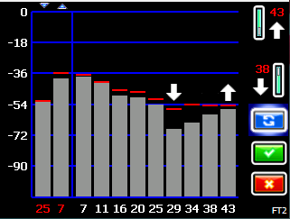
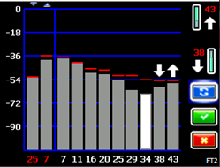
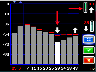
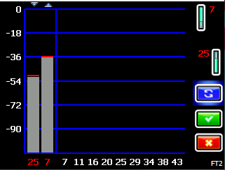
When the noise bars appear, walk your intended drill path while observing the bars and their high-point markers. Pay special attention to the deeper parts of the bore. Consider rescanning the location if the noise is high.
Higher bars and markers indicate more noise. The white arrows indicate the two lowest high-points and the options for quick pair.
Return to the point of most noise and click to rescan.
This gives you the best frequencies for this location.
You can continue to use the current bands, or use either the Quick Pick selections or select one or both new bands manually.
To continue using the currently paired bands, click Cancel.
Select Pair to pair the Up and Down bands with the two bands indicated by the two white arrows.
FO Wideband Screen
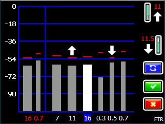
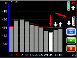
If you are using a FTR Sub-K transmitter the FO includes low frequency bands.
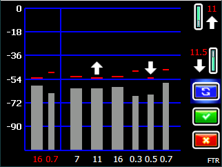
Sub-K Frequency Optimizer Screen
You can select 7, 11, or 16 for the Up band with Standard power and 0.3, 0.5, or 0.7 for the Down Band with Low power.
FTR Sub-K transmitters do not support adjustable power modes.
The Up and Down bands are assigned with the two bands marked with the Up and Down arrows.
The red band numbers turn green with an asterisk to indicate the bands that will replace the previously selected bands.
To manually select one or both bands, toggle to the band you want to use, click to select. The band number next to the Up arrow turns green with an asterisk to show this is the selected band. Click again to assign it as the Up band, or toggle down to assign to the Down Band.
The band numbers turn green and add an asterisk to indicate the selected Up or Down bands that will replace the previously selected bands.
If you are using a FTR Sub-k transmitter the FO includes low frequency bands.
You can select 7, 11, or 16 for the Up band with Standard power and 0.3, 0.5, or 0.7 for the Down Band with Low power.
FTR Sub-k transmitters do not support adjustable power modes.
If needed, select and assign the other band.
Pairing sends the frequencies you selected to the transmitter. Pair a transmitter immediately after scanning and picking bands with one of the Advanced methods.
Insert battery(ies) positive terminal first and install the battery cap to power on the transmitter.
To pair any other time, from the Main menu select Transmitter selection,
Frequency optimization, and continue.
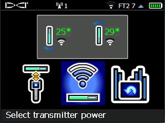
Confirm the Up and Down band and the power modes.
To change the transmitter power mode, select Select Transmitter Power. Select the power mode you want to change, and then toggle up or down to change.
Align the transmitter so its IR port is near and facing the round IR port on the front of the locator.
The Falcon Plus locators ignore the V2 Power Mode selection method described on the transmitter sticker and use the locator-specified power level.
Select Transmitter pairing request.
After a successful pairing, click to calibrate.
The "Li/3V Only" warning appears if you are not using the recommended Lithium rechargeable or SuperCell battery and have selected a High power mode.
If you are using a V1 transmitter, a warning reminds you that it only uses Standard power mode.
Calibration is required any time you change your transmitter, locator, drill head, power setting, or perform a new frequency scan and then pair.
Calibrate both bands with the transmitter in the housing (flat on the ground in a low-noise, metal-free environment) immediately after pairing.
To calibrate any other time, from the Main menu select Calibration, then 1 pt calibration before continuing with the following steps.
Watch video on YouTube:
Calibrate Your DCI Transmitter and Locator (1:28 min)
Install the powered-on transmitter in the drill head. Place the cover on, but don’t fasten it yet.
Using a tape measure, place the near edge of the locator parallel to and exactly 10 ft (3 m) from the center of the transmitter.
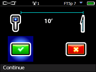
For accurate calibration, always use the center of the transmitter, not the drill head.
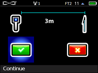
Select Continue to calibrate the Active band.
If you are pairing both bands, the Up band is calibrated first.
The locator beeps 3 times fast and displays a check mark after a successful calibration.
Use the Above Ground Range (AGR) that displays next to check the accuracy of your calibration. Move the locator to at least two different distances (5 ft/1.5m and 15 ft/4.6 m) and verify distance readings match the measurement.
The locator assumes the transmitter pitch equals zero during the above ground range check. For accurate readings ensure the transmitter is approximately level.
Click Cancel to exit to the Locate Mode screen where you will see clock, pitch, and signal strength.
To change the transmitter to the Down Band, hold the Tx at the same (±2) general clock position (CP) for this whole procedure.
Hold transmitter powered on at level (0±10°) for at least five seconds.
Tilt transmitter up at approximately +65° (almost vertical) for 10-18 seconds.

Return to level for 10-18 seconds.
When the transmitters changes bands, data disappears from the locator.
You can also use the Power-on Method described in "Change Transmitter Band, Power-On Method" in the Advanced Topics chapter.
To change the locator to the Down band, from the Locate Mode screen, hold toggle right to open Band Selection shortcut menu, and then select the desired Down band.
Select Locate Mode and verify that you see the clock, pitch, and signal strength.
The red triangle in the roll indicator shows calibration is needed.
From the Main menu, select Calibration.
Select 1 pt calibration.
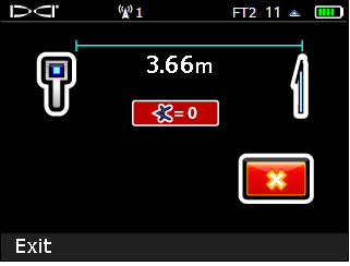
Put the transmitter back in the drill head, put the cover back on, and ensure the near edge of the locator is still parallel to and exactly 10 ft (3 m) from the center of the transmitter.
For accurate calibration, always use the center of the transmitter, not the drill head.
Select Continue to calibrate the Down band.
The locator beeps three times and displays a check mark after a successful calibration.
Use the Above Ground Range (AGR) that displays next to check the accuracy of your calibration. Move the locator to at least two different distances and verify distance readings match the measurement.
Click Cancel to exit to the Locate Mode screen. Verify you see clock, pitch, and signal strength.
Fasten the drill head cover properly before drilling.
Things You Should Know
HAG must be turned on manually each time after the locator is powered on or calibrated.
Target Steering assumes that the locator is on the ground, even if standard HAG is enabled. If TrakStand HAG is enabled the height set for the Trakstand is adjusted for Target Steering.
From the Main menu, select HAG.
To enable standard HAG (hand-held), toggle to Enable HAG. If the height shown at the bottom of the screen is acceptable, select Enable HAG. Otherwise, click Set HAG to enter a new height.
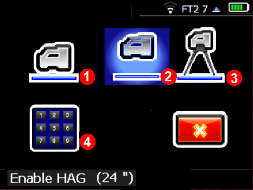
- Disable HAG
- Enable standard HAG
- Enable TrakStand HAG
- Set HAG
The locator must be held at this height for accurate depth readings. TrakStand height can be used with Target Steering.
a. To enable TrakStand HAG, toggle to Enable TrakStand. Confirm the height. The height is preset to 0.46m.
- The height of a TrakStand with legs fully extended is 1' 6" (0.46m).
- The height of a Trakstand with legs fully collapsed is 1'9" (0.60m).
b. Select Enable TrakStand.
It is not recommended to change the TrakStand Height. If needed, Enable Trakstand, return to the Enable HAG screen, and then select Set HAG to enter a new height. The custom height will revert back to the pre-set (1'6"/0.46m) after a power cycle.
The locator must be in the TrakStand at the set height for accurate depth readings.
Find the Rear Locate Point (RLP)
After the first rod has been drilled in, start at the entry point and face the direction of the bore.
Using the Locate Mode screen, move the locator to put the ball in the box.
- Ball
- Box
Mark this position on the ground as the Rear Locate Point (RLP).
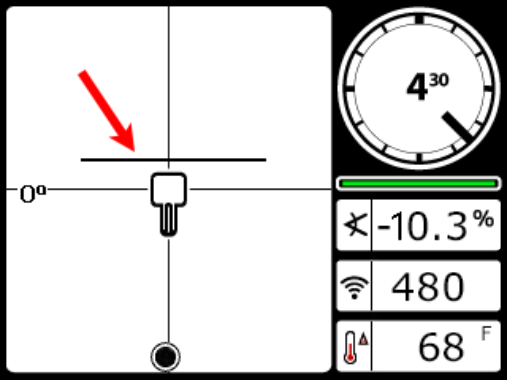
Find the Front Locate Point (FLP)
Walk forward. As you pass the transmitter, the ball jumps to the top of the screen. You are now tracking the Front Locate Point (FLP).
The signal strength increases as you move toward the transmitter and decreases as you move away from it.
An A near the roll indicator indicates signal Attenuation is in effect. If the signal strength is red and flashing, this indicates extreme interference.
Move the locator to put the ball in the box.
The locator can face toward or away from the drill as long as it is parallel to the direction of drilling.
Mark this position on the ground as the Front Locate Point (FLP).
Hold the trigger to show the predicted depth * of the transmitter at this location.
Hold the trigger for at least one second. The R indicates the signal is locked. The LL will not appear without the reference lock.
Look back toward the RLP. The transmitter housing is positioned to travel toward you along the line connecting the RLP and FLP.
Find the Locate Line (LL)
Walk back toward the RLP until the Locate Line (LL) appears.
If the LL does not appear, go to the FLP and hold the trigger to show the predicted depth until the R appears.
Ensure the locator is on the line connecting the two marked locate points. Position the locator so the LL passes through the center of the box. The transmitter housing should be beneath this point as long as the transmitter is relatively level (see "Steep and Deep" under Advanced Topics).
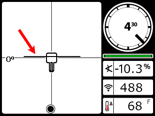
The locator can face toward or away from the drill as long as it is parallel to the direction of drilling.
Hold the trigger to take a depth reading.
If the signal strength is red and flashing, this indicates extreme interference. If you hold the trigger for longer than five seconds, the locator will enter Max Mode *, which can help with unstable data caused by interference or extreme depths.
Continue Locating as the Drill Head Moves
After the drill head moves forward another rod, find the new RLP, FLP, and then the LL.
If the new FLP is in line with the prior locate points (a straight bore line), it is unnecessary to find a new RLP. For a curved drill path, always identify both the FLP and RLP.
If you have a straight drill path but the FLP is to the left or right of the line projected from the previous locate points, this may indicate a drill head deflection or interference affecting the transmitter’s signal.
The Predicted Depth screen displays when the trigger is held with the locator at the Front Locate Point (FLP). The predicted depth is how deep the transmitter is calculated to be when it reaches the front locate point if it continues on its current path. The predicted depth will also display when the locator is at the Rear Locate Point (RLP), but it will not be correct.
Max Mode can stabilize roll/pitch data and depth readings when drilling at the transmitter’s range limit due to extreme depth or interference, which will vary by jobsite. See the Max Mode topic for use and important safety information.
Stuff You Should Know
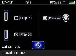
Switching bands on the transmitter may provide better data, better depth, and/or better locate results as interference conditions change.
Calibrate BOTH bands before drilling so you get accurate depth readings on both bands.
Observe signal strength drop after the drill operator completes a roll sequence to change bands.
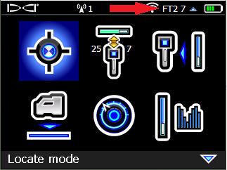
From the Locate Mode screen, hold toggle right to open the Band Selection shortcut menu.
Toggle to and select the transmitter band without the X in the box (in this case, FT5p 7).
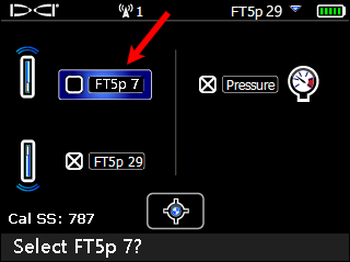
Select Locate Mode.
You can use your locator to display the degree or percentage of pitch of the terrain.
Place the locator on the ground.
To take a measurement on a slope, tilt the locator left or right so that the display screen is level.
From the Main menu, toggle down to the second page and select Diagnostics.
Select Perform Level Check.
The pitch is displayed in degrees or percent.
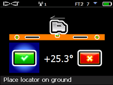
To exit, click Cancel.
Watch a video and learn more.
Some videos are only available in English. Please turn on subtitles and automatic translation.
Watch video on YouTube:
DigiTrak - Falcon F5 Training - How to display surface grade (1:23 min)
Select power icon in the second page of the Main menu to power off the locator.
Remove the battery and inspect its contacts and those inside the battery compartment for corrosion and debris. Clean and charge as needed.
Wipe the locator clean. Use only an abrasive-free cleaner and soft cloth to clean the screen.
Do not pressure wash.
Store the battery and locator in the original system carry case safe from impact, moisture, and excessive temperatures.
Do not store the battery in the battery charger or locator.
Storage and transportation temperature must remain within -40° to 149°F (-40° to 65°C).
Remove the transmitter from the drill head.
Wipe the transmitter clean so dirt doesn’t enter the battery compartment or accumulate on the battery cap threads.
Remove the transmitter batteries to power it off.
The transmitter records active run-time for warranty purposes. Sleep mode is not counted.
Inspect the battery compartment, springs, cap, O-ring, battery adapter, and threads for debris. Clear any debris and replace the battery cap.
Use conductive lubricant on the threads if the battery cap is difficult to turn.
Store batteries so they do not contact metallic objects or terminals of other batteries.
Store the transmitter in the original system carry case where it will be safe from impact and excessive temperatures.
Storage and transportation temperature must remain within 40° to 149° F (-40 to 65 °C).
When a transmitter is level (zero pitch) underground:
- the locate points (FLP and RLP) are at equal distances from the transmitter
- depth displayed on the locator is the actual depth, and
- the Locate Line (LL) indicates a position above the transmitter.
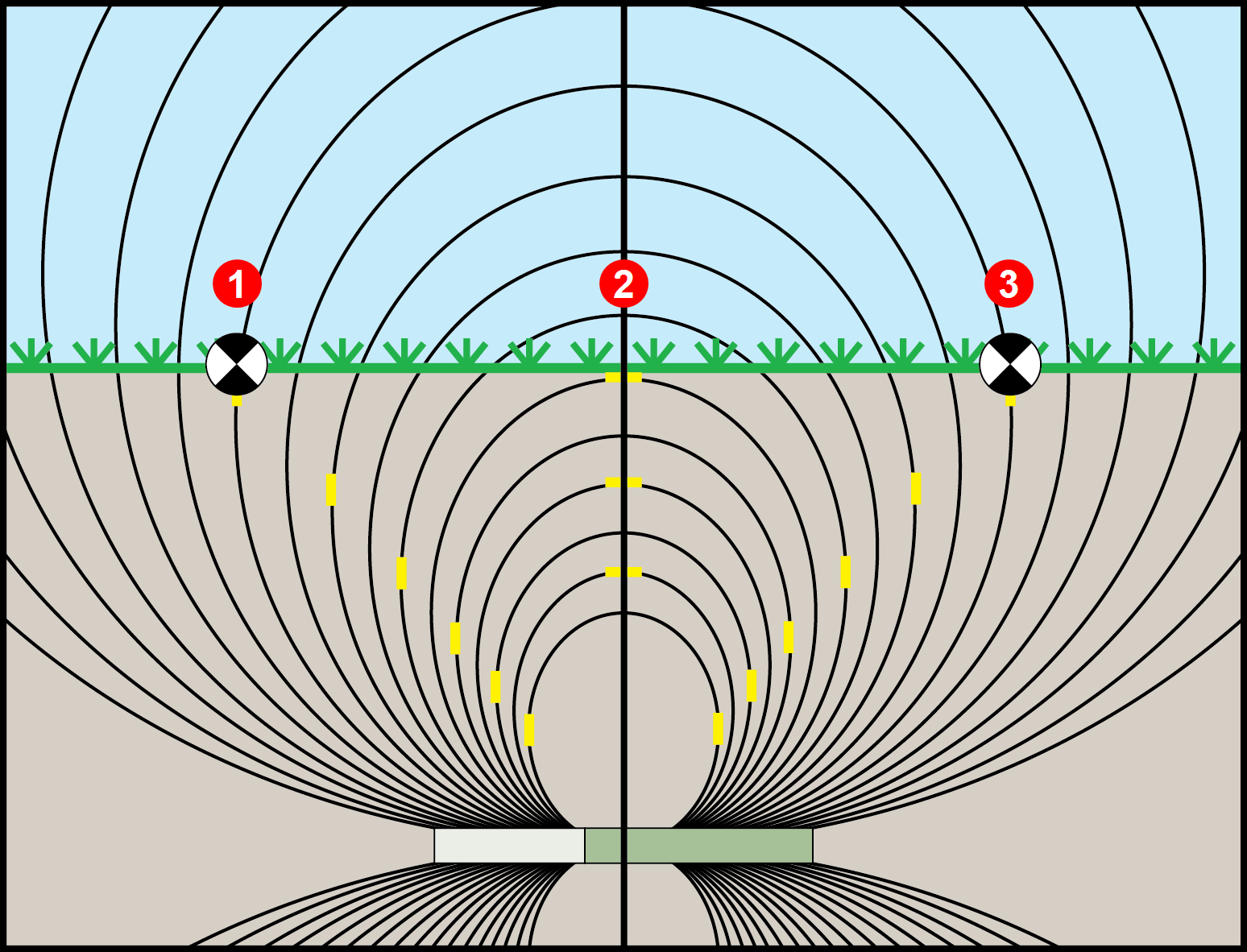
- RLP
- LL
- FLP
When the transmitter is pitched up or down, the transmitter signal field also tilts.
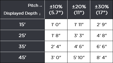
When the transmitter is pitched down (negative pitch), the locate line on the screen reflects a future position of the transmitter, assuming the transmitter stays on the same trajectory (projected depth).
When the transmitter is pitched up (positive pitch, shown below), the locate line on the screen reflects a position behind the transmitter.
The depth reading on the locator is based on the projected depth point, which is not the same as the actual depth of the transmitter.
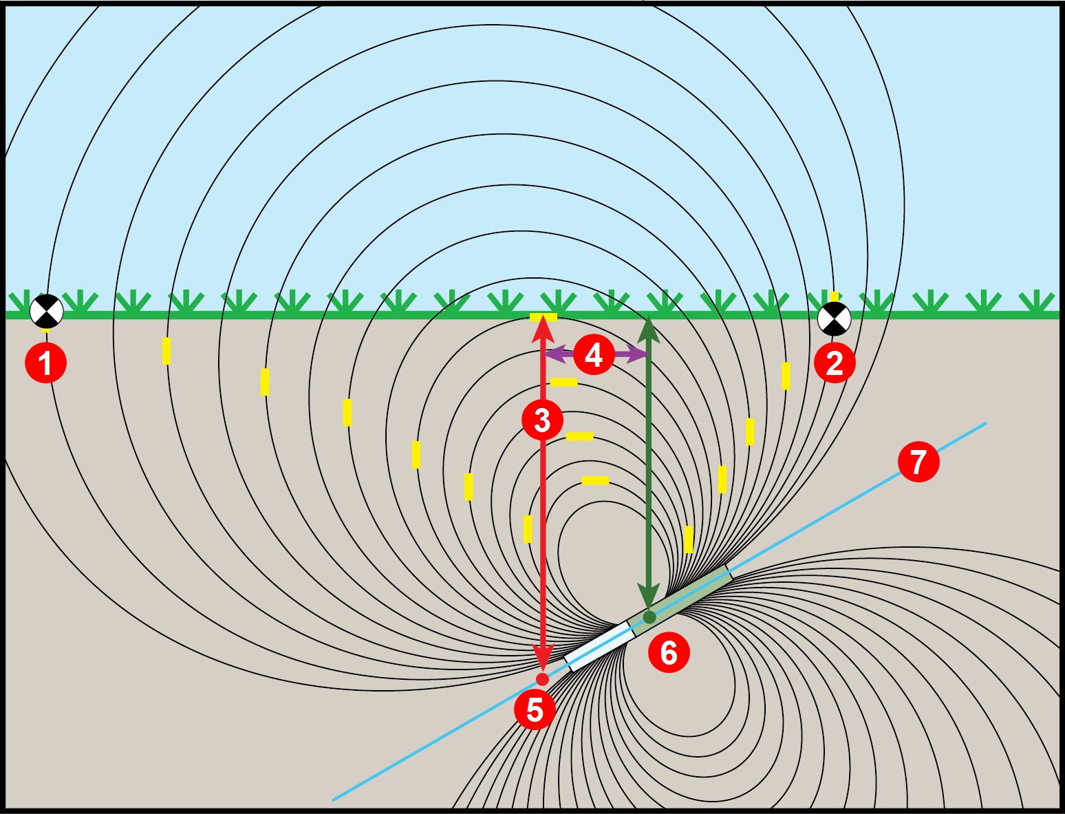
- RLP
- FLP
- LL
- Fore/aft offset
- Projected depth
- Transmitter at positive pitch
- 30% (17°)
The differences in position and depth between the projected depth point and the actual location of the transmitter can be relatively small at low pitch and/or shallow depth.
When drilling at a steep pitch and/or significant depth, the differences are greater.
For example, if the transmitter is at a plus or minus 30% pitch and a 33'1" (10.1 m) depth, the locator depth reading will be 35' (10.7 m) (just under 6% difference from actual depth) and the locate line will be 6'6" (2 m) from being directly above the transmitter (-30% places the LL ahead and +30% places the LL behind).
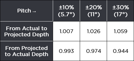
You can use the pitch and the projected depth reading on your locator to determine the actual depth and the position (fore/aft) of the locate line:
Actual Depth
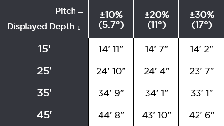
Fore/Aft Offset
For a given pitch, you can calculate actual or projected depth:
This calibration procedure is rarely needed. If you find it necessary to calibrate with the transmitter in the ground, contact DCI customer service for information on this option, and perform the procedure with caution.
Before You Get Started
Max Mode can stabilize roll/pitch data and depth readings when drilling at the transmitter’s range limit due to extreme depth or interference, which will vary by jobsite. Use when the roll/pitch update meter shows low signal level or data is unstable.
The drill head must be stationary when taking readings using Max Mode. If the drill head is moving, data readings will not be accurate.
At the Locate Mode screen, hold the trigger for longer than five seconds to enter Max Mode.
Continue holding the trigger until depth and data stabilize.
If the Max Mode timer fills up before depth and data stabilize, move to a different location near the drill head and hold to restart.
The timer bar will turn green as data is confirmed.
- Depth
- Max Mode icon
- Max Mode timer
- Transmitter battery strength
Take two more Max Mode readings. All three readings must be consistent.
If the readings are not consistent, change the band and try again. If the readings continue to be inconsistent, turn the locator off and then on again. If the issue continues, contact DCI Customer Support.
Before You Start
Use the Roll Offset menu when the 12 o’clock position of the transmitter cannot be indexed to that of the drill head. Roll offset lets you program the locator to display the roll of the drill head rather than that of the transmitter.
On the Locate Mode screen, the roll indicator will change to a circle, and “RO” appears at the bottom left of the roll indicator.
To set the roll offset, at the Locator Main menu, select Settings,
then Roll Offset.
Select Set and Enable Roll Offset from the Roll Offset Menu.
Ensure the drill head is at its 12 o’clock position and that the transmitter is on. Note the roll value showing on the screen.
With the Set roll offset option highlighted as shown, click the trigger to set the roll offset. The locator will beep four times as the screen returns to the Settings menu with roll offset enabled.
On the Locate Mode screen, the roll indicator will change to a circle, and “RO” appears at the bottom left of the roll indicator.
If the locator does not detect a roll signal from the transmitter, the roll offset operation fails.
Click the trigger to retry setting the roll offset or toggle right to select exit and return to the settings menu. If the roll offset failure screen appears, verify the setup and try again or contact DCI Customer Service.
Disable Roll Offset
To turn off the roll offset function, select the disable roll offset option from the roll offset menu.
The locator beeps four times as the screen returns to the Settings menu. The value that displays for roll on the Locate Mode screen will now be that of the transmitter, not necessarily the drill head.
The Target Steering guidance method allows the locator to be placed ahead of the drill head and used as a steering target.
Use it to distance the locator from rebar that is causing signal interference and to drill where walkover locating is not possible.
Target Steering is typically used on a straight drill path, not on a curved bath, terrain changes, or to correct a significantly off-course bore.
You can set a target depth and then use Target mode with left/right and up/down steering accurately up to 35 ft (10.7 m). After this range, you can still use left/right steering (remote steering) for the entire range of the transmitter.
Target Steering assumes that the locator is on the ground or at the height set with a TrakStand with HAG enabled. The locator ignores the handheld Height-Above-Ground (HAG) setting.
Toggle up from the Locate Mode screen.
The number on the screen shows the last target depth * set. If it matches your desired target depth, select the checkmark.
To change the target depth shown, use the keypad.
If TrakStand HAG is enabled, but drilling shallower than 1.5 ft (0.5 m), adjust the TrakStand HAG height.
If using standard HAG and holding the locator to distance from rebar or drilling shallower than 1.5 ft (0.5 m), add the height to the target depth since standard HAG is ignored for Target Steering.
Place the locator on the drill path with its battery compartment facing the drill head. Target Steering guides the transmitter to be inline with the locator's handle when it reaches the target beneath the locator. For accurate depth information, use the horizontal distance reading on the Target Steering display to ensure the locator is no more than 35 ft (10.7 m) in front of the transmitter.
If you go past 35 ft (10.7 m) do not rely on the depth and up/down steering information. Instead, monitor pitch data.
- Horizontal distance from transmitter to locator
- Current transmitter depth below the plane of the locator
At this point, the drill rig operator uses the remote display to drill to the target.
When the horizontal distance is almost the same as the current depth, move the locator farther out to continue Target Steering.
If the drill head passes this point, depth and horizontal distance values on the Aurora become invalid.
From the Locate Mode screen, toggle down to turn off Target Steering.
A value programmed into the locator, so it can be positioned ahead of the transmitter housing and used as a steering target. The value programmed should be the desired depth of the transmitter when it reaches the point below the locator. If a locator is placed above ground level, such as to provide separation from interference, that height must be added to the target depth.
Note: If using a Falcon Compact Display, only left/right steering information is available. The locator used with the Falcon Compact Display must still have a target depth set. This target depth can be any value.
Things You Should Know
Full Scale Sensitive Pitch (FSSP) provides pitch information on your F5+ locator when used with a 15-inch or 19-inch transmitter.
The default Standard Pitch range for Falcon transmitters is +90% to -90%. The Standard Pitch Resolution chart * lists standard pitch ranges and the corresponding pitch resolution.
To change the default, use Full Scale Sensitive Pitch. The pitch range is +99.9% to -99.9% and the resolution will be in 0.1% increments throughout. The Fluid Pressure Resolution chart * lists the pitch resolution.
These charts are also available in the Reference chapter.
To enable full scale sensitive pitch resolution, go to Settings, toggle down to the third screen and select Full scale sensitive pitch enabled.
Selecting 0.1% pitch increments decreases fluid pressure resolution.
To set the pitch units, go to Settings, select Pitch units in degrees, and then select percent or degrees.
Falcon F2 and older Falcon F5 transmitters do not support FSSP mode and will not work in FSSP mode even if selected.
Resolution at:
• 0 – 3% grade (0 – 1.7°) is 0.1%
• 3 – 9% grade (1.7 – 5.1°) is 0.2%
• 9 – 30% grade (5.1 – 16.7°) is 0.5%
• 30 – 50% grade (16.7 – 26.6°) is 2.0%
• 50 – 90% grade (26.6 – 42.0°) is 5.0%
Standard resolution:
from 0–75 psi is 1 psi
from 75–250 psi is 5 psi
Resolution after selecting Transmitter pairing request 0.1% / 100% (Full Scale Sensitive Pitch, FSSP) for a compatible Falcon F5 transmitter:
from 0–50 psi is 5 psi
from 50–150 psi is 10 psi
from 150 – 250 psi is 20 psi
"Find Best Frequencies" in the Jobsite Setup chapter describes how to run the frequency optimizer, walk the bore to scan for interference *, then optimize both bands at the point of highest noise. You need to be familiar with that topic before reading this one.
For jobsites with extra-challenging interference, consider a scan-pick-pair of the first band at the noisiest point (such as next to the power transformer), then scan-pick-pair the second band at the second-noisiest point (such as over railroad tracks). This gives you a specifically tailored band for each of the two most difficult locations along your drill path.
To use different scans for the Up and Down bands, you must pair the first band before scanning for a second band.
Ensure all transmitters are powered off or more than 100 ft (30.5 m) away from the locator.
From the Main menu, select Frequency optimization.
Click the blue arrow to start the scan.
When the noise bars appear, walk the intended drill path to find the two locations with the highest levels of noise, then return to one of those locations and scan again.
Toggle to the band with the least noise *, click to select, then click again to assign it as the Up band.
Before assigning the down band, pair the Up band to the transmitter. Otherwise, rescanning will erase the current frequencies.
Select Pair to pair and select power level. Skip calibration.
Move to the other location with high noise, return to Frequency Optimization, and scan again.
Toggle to the lowest band, click to select, then click again to assign it as the Down band.
Before assigning the Down band, you must pair the Up band to the transmitter. Otherwise rescanning will erase the current frequencies.
Select Pair to pair and select power level for the Down band before proceeding to calibration as you normally would when pairing both bands at one location.
Your locator can only detect active interference, not passive interference, such as rebar. Lower frequency bands tend to perform better around passive interference. Middle bands can perform better in deeper bores and may have longer Target Steering capability. High bands have slightly less signal strength, but tend to offer better performance around active interference such as power lines.
Interference varies with time and location, and no band works perfectly in all conditions. Different bands are better for different kinds of interference. Lower frequency bands tend to perform better in passive interference. Middle bands can perform better in deeper bores and may have longer Target Steering capability. Higher frequency bands have slightly less signal strength but tend to offer better performance around active interference such as power lines.
To change the transmitter band, hold the Tx at the same (±2) general clock position for this whole procedure.
Hold transmitter powered on at level (0±10°) for at least five seconds.
Tilt transmitter up at approximately +65° (almost vertical) for 10-18 seconds.
Return to level for 10-18 seconds.
If the locator is on the same band as the transmitter, data will appear on the locator screens.
To change the band on the locator, from Locate Mode screen, hold the toggle right to open the Band Selection menu. Select the band without the checkmark. After a few seconds, data will begin to appear.
Remove the batteries from the transmitter and observe the data disappear from the locator.
To change to the Down band, hold the transmitter vertical with the index cap end pointing straight down. Insert the batteries and reinstall the battery cap to power on the transmitter. Keep the transmitter vertical for 4-5 seconds.
The band being used on the transmitter must match the band on the locator. If no data is displayed on the Locate Mode screen, hold the toggle to the right to open the Band Selection shortcut menu.
From the Main menu, select Transmitter selection.
Select Transmitter information.
Align the transmitter so its IR port is near and facing the round IR port on the front of the locator.
The transmitter does not need to be paired for the locator to read the transmitter info.
Select Transmitter Information request.
Use the Transmitter Info screen to check important information such as runtime hours for warranty coverage, current band (green), operating current *, battery voltage *, and max recorded temperature.
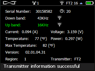
Click to return to the Main menu.
A reading of greater than 0.50 A or less than 0.05 A indicates electrical failure.
A voltage reading below 2.7 (alkaline), 3.2 (lithium) or 3.9 (LiR) indicates bad or depleted batteries.
V2 Transmitters have three power modes to balance signal strength and battery life. V2 transmitters are etched with a "V2" on the stainless battery compartment (not on the label) and have a multipower mode sticker around the IR port.
If used with a Falcon without the programmable power mode, the mode selected while pairing the Tx determines the signal range and the battery life.
Falcon locators with programmable power mode override any other selection method when used with a V2 transmitter.
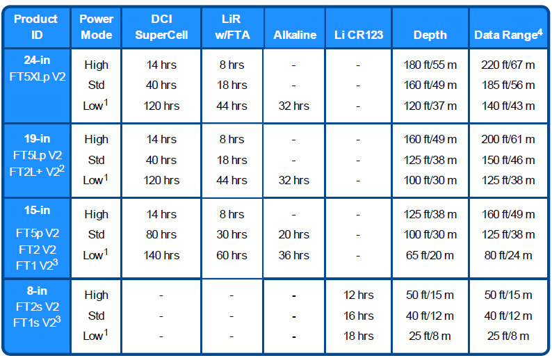
1 For Falcon locators with programmable power mode, Low power also gives you a faster pitch update rate
2 FT2L+ V2 is only compatible with Falcon+ locators.
3 F1 Low and standard power only
4 Range is based on SAE Standard J2520 in AGR mode and Max Mode. Actual range and battery life will vary based on interference, transmitter housings, and frequencies.
The battery types listed are the only types recommended for that model and size. DCI does not recommend using other battery types. *Lithium Rechargeable (LiR) battery life is based on 21700 battery with 5000 mAh rating. with a max 4.2 volts. Battery life while asleep is 400 hours for SuperCell and 200 hours for alkaline. Sleep mode starts 15 minutes after last roll change.
FTR (Sub-k Rebar) Tx's do not have MultiPower mode and have Standard power battery life. Depth/data range for Up Band is similar to Standard power; Down band is similar to Low power mode.
You can see the power mode selected for each band on the Transmitter Info screen. See "Get Transmitter Info" for steps.
You can also see the Power mode of the current band on the Locate Mode screen and the TX Info pairing screen.
From the Main menu, go to Transmitter Selection.
Select Frequency Optimization. The Frequency Optimizer displays the two currently selected bands.
To skip rescanning and use the current bands, on the Frequency Optimizer, click Pair.
The Up and Down bands will not change. If you also want to change one or both bands, select the Rescan icon.
Select Transmitter Power.
Falcon locators with programmable power mode override any other selection method when used with a V2 transmitter. Use the locator to change the power mode.
Toggle to the band (Up or Down) that you want to change, and then click to select.
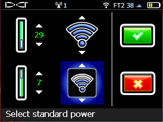
High Power requires Lithium-ion batteries.
Toggle up or down to toggle through the High, Standard, and Low power modes, and then click to select the new power level.
For High power mode, Lithium-ion batteries are recommended.
For V1 transmitters and FTR transmitters, High power is ignored and the transmitter will pair at Standard power.
Select Confirm.
Select Transmitter Pairing request.
If FSSP is enabled, the Pairing icon includes the pitch symbol.
Continue to pair and then calibrate the transmitter.
For step-by-step instructions, see the articles, "Advanced FO - Pair" and "Calibrate Intro" in the Jobsite Setup chapter.
After changing the power level, you must re-pair the transmitter and then perform a 1 PT Calibration for each band changed. For step-by-step instructions, see the articles "Advanced FO - Pair" and "Calibrate Intro" in the Jobsite Setup chapter.
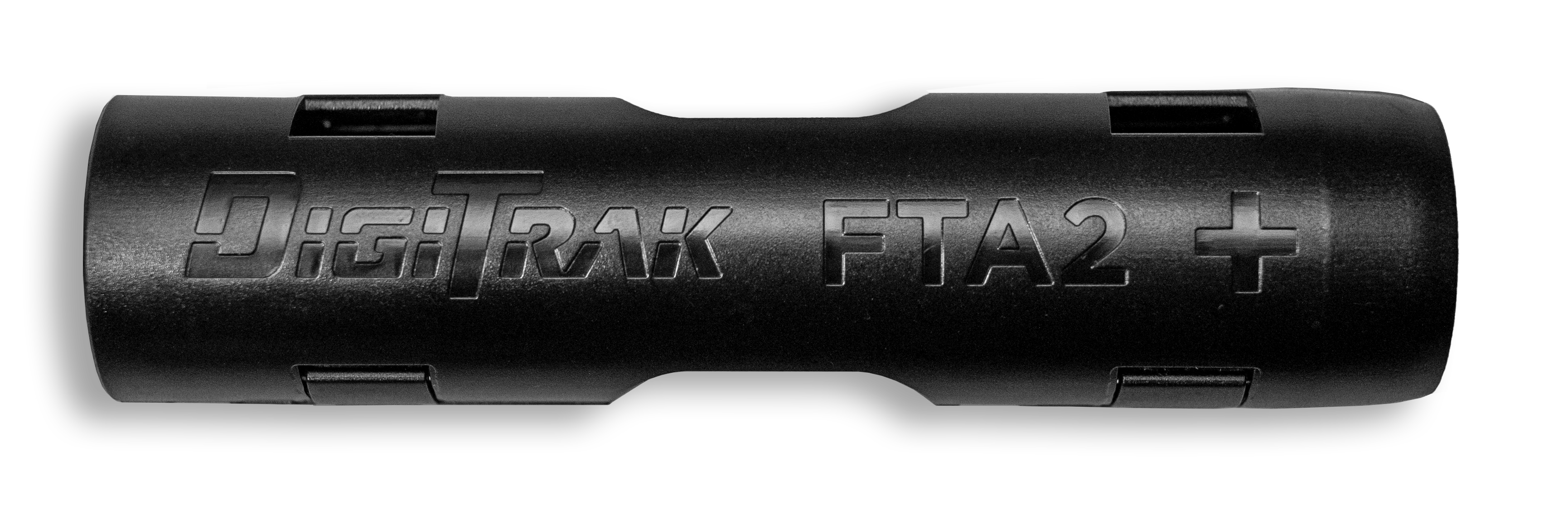
FTA2 Falcon Transmitter Adapter is designed specifically for a single 21700 LiR (Lithium Rechargeable) battery with built-in protection. Falcon transmitter runtime estimates are based on use of a 5,000 mAh battery with a max 4.2 volts. This adapter incorporates a lockout and is designed to fit the Blue DCI Falcon Transmitters.
The FTA is not compatible with Falcon transmitters with green tubes.
For a 21700 battery, insert the positive terminal first.
Battery Life
19-Inch Blue V2 MultiPower Transmitters
- High power: 8 hours
- Standard power: 18 hours
- Low power: 44 hours
15-inch Blue V2 MultiPower Transmitters
- High power: 8 hours
- Standard power: 30 hours
- Low power: 60 hours
Lithium Rechargeable (LiR) battery life is based on 21700 battery with 5000 mAh rating with a max 4.2 volts.
For more information on MultiPower transmitters, see "V2 Transmitters MultiPower Mode Introduction."
DCI suggests the following top tier manufacturers for LiR batteries. Diameter should not exceed 22mm with a length of 75.5mm +/-1mm. Other LiR models may not fit or be as likely to survive the rigors of HDD.
Recommended Manufacturers
Klarus Part number: 21GT-50
Fenix Part number: ARB-L21-5000
Acebeam Part number: IMR21700NP-510A
DigiTrak transmitters (Tx), with the exception of DucTrak, have temperature overheat indicators (temp dot) on the front end cap.
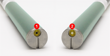
- Black temp dot (voids warranty)
- Normal white temp dot
The temp dot has an outer yellow ring with a temperature-sensitive 1/8" white dot in the center. If the center temp dot is black, the transmitter has been exposed to excessive heat and should no longer be used.
The DCI Warranty does not cover any transmitter that has been overheated or had the temp dot removed.
DigiTrak transmitters (Tx), with the exception of DucTrak, have an internal digital thermometer. The normal below ground temp range is 63° to 104° F. The Tx temperature displays on the bottom of the locator screen and remote display screens.
- Temperature status icon
- Temp trend up/down arrows
- Temperature
Suspend drilling when temperatures increase rapidly. Temperatures above 111° F are not typical.
As the transmitter (Tx) temperature increases above 61° F, the locator and remote emits warning beeps and the temperature icon changes on the locator or remote display.
Tx temp: 61° to 97° F
Warning tones: Double beep (beep-beep) for every 7° F increase.
Watch for an upward trend in temperatures.
Tx temp: 104° to 111° F
Warning tones: Two double beeps (beep-beep; beep-beep) for every 7° F increase.
Cool the transmitter.
Tx temp: 118° to 133° F
Warning tones: Three double beeps (beep-beep, beep-beep, beep-beep) for every 7° F increase.
Cooling is critical to avoid irreversible damage.
Tx temp: 140° F and above (icon flashing)
Warning tones: Three double beeps (beep-beep, beep-beep, beep-beep) for every 20 seconds on the locator and 5 seconds on the remote display.
The transmitter has been exposed to dangerous drilling conditions. Temperatures above 185° F may cause irreversible damage to the transmitter.
The transmitter records the maximum temperature that it has been exposed to. Use the Transmitter Info screen to view this information. See "Get Transmitter Info" for steps.
Double-check that your transmitter is powered on
a. Roll the transmitter 180°. Transmitters will fall asleep after 15 minutes of inactivity.
b. If you do not have data and the transmitter is above ground, move the transmitter close to the locator.
If the signal strength increases try the next solution. If not, insert fresh batteries. Lithium batteries will show 100% up until they’re nearly depleted.
Make sure you have the correct frequency band selected
a. Start at the Locate Mode screen, hold the toggle to the right.
b. Toggle up to select whichever frequency is not currently in use (frequency without an ‘x’).
c. Click Locate Mode to return to the Locate Mode screen. If Roll/Pitch data appears, the transmitter was powered up in another frequency.
Check that the Transmitter is working.
a. Check that you can view the transmitter info. If you can view data, the Tx is powered on, working, and can be paired. If you cannot view this screen, the transmitter may be damaged.
The transmitter does not have to be paired to the locator to view the transmitter info.
b. In the Tx Info screen, verify that the locator is using the correct transmitter type (FT2, FT5, or FTR). If needed, change the transmitter type.
c. The Active band (Up or Down) appears green.
For step-by-step instructions, search for "transmitter info" and "Change transmitter type."
Re-Optimize and Pair your transmitter.
If you have a new transmitter, or locator, you must optimize, pair your frequencies, and recalibrate.
For step-by-step instructions, go to Find Best Frequencies in the Jobsite Setup chapter.
If you still don't have roll and pitch data, call DCI for further troubleshooting.
Check that the correct transmitter is selected.
a. On the Main menu, select Transmitter Selection.
b. Select Transmitter and then select the transmitter model.
The transmitter’s model is etched on its battery compartment.
Double-check that your transmitter is powered on.
a. Roll the transmitter. Transmitters will fall asleep after 15 minutes of inactivity.
b. If you do not have data and are above ground, insert fresh batteries. Lithium batteries will show 100% up until they’re nearly depleted.
Perform a Transmitter Information Request.
a. On the Main menu, select Transmitter Selection.
b. Select Transmitter Info.
c. Hold the flat section of your transmitter near the black IR port on your locator.
d. Click Transmitter Information Request.
Pay attention to battery voltage as yours may be low/dead. Lithium Rechargeable (LiR) battery should read between 4.2V and 4.0V, if new. SuperCell should read between 3.6V and 3.4V, if new. Alkalines should read between 3.2V and 3.0V, if new.
Replace the batteries with recommended brands and perform another transmitter information request.
Recommended brands are two C-cell Energizer alkaline batteries, two 21700 LiR (rechargeable) batteries, or one DCI SuperCell lithium battery.
If you are still unable to pair the transmitter, call DCI for further troubleshooting.
Verify that both units are set to the same telemetry channel.
Under the same locator icon on the Aurora you’ll find a symbol that looks like a cell tower which represents four telemetry channels. These must be set to the same channel for the remote and the locator.
a. To change channels on your locator, toggle down into the main menu and select Settings.
b. Toggle to the telemetry icon and make sure the locator icon matches your remote.
Verify that your display on the drill is set to the correct locator.
To change what locator your remote looks for click the main menu icon and then on the locator icon under Settings.
Verify that your display on the drill and the locator are set to the same World Region.
You can change the World Region on the remote display, but not on the locator.
Check any external antenna on the remote display for damage.
Ensure all internal pins are intact and clean with alcohol if connection points look dirty.
If not already in use, a filtered antenna may be necessary to reduce the effects of interference in the area.
Call DCI for further troubleshooting.
Product ID: FF5+
Model number: FAR5
Receiving frequencies: 0.33 to 45.0 kHz
Accuracy (1): ±5% of depth reading
Telemetry channels (2): 4
Telemetry range (3): Up to 3000 ft (900 m)
Target steering range (4): 35 ft (10.6 m)
L/R steering range: Range of transmitter
Power source: Lithium-ion battery pack
Battery life: 8–12 hrs
Functions: Menu-driven
Controls: Trigger and toggle switches
Graphic display: Full-color LCD
Audio output: Beeper
Voltage, current: 14.4 VDC nominal, 390 mA max
Operating temperature: -4 to 140° F (-20 to 60° C)
Dimensions: 11 x 5.5 x 15 in (27.94 x 13.97 x 38.1 cm)
Weight (with battery): 8.4 lb (3.81 kg)
Compatible Transmitters: See the article "List of Compatible Transmitters."
Compatible Displays: Compatible remote displays: Aurora and FCD
(1) Over specified depth range for each transmitter model.
(2) Local telemetry frequencies and power levels available at digital-control.com.
(3) Telemetry range is dependent upon the remote display and optional external receiving antenna.
(4) Requires an Aurora Display.
COMPLIANCE
This equipment complies with the following: Part 15 of the Rules of the FCC; Innovation, Science and Economic Development Canada's license exempt RSS(s); ACMA Radio Communications Standard (2021) as found in ACMA Radio Communications Equipment General Rules (2021). Operation is subject to the following two conditions: (1) this equipment may not cause harmful interference, and 2) this equipment must accept any interference received, including interference that may cause undesired operation.
L’émetteur/récepteur exempt de licence contenu dans le présent appareil est conforme aux CNR d’Innovation, Sciences et Développement économique Canada applicables aux appareils radio exempts de licence. L’exploitation est autorisée aux deux conditions suivantes : 1. L’appareil ne doit pas produire de brouillage; 2. L’appareil doit accepter tout brouillage radioélectrique subi, même si le brouillage est susceptible d’en compromettre le fonctionnement
DCI is responsible for FCC compliance in the United States. Changes or modifications to any DCI equipment not expressly approved and carried out by DCI will void the user’s Limited Warranty and the FCC’s authorization to operate the equipment.
Digital Control Incorporated
19625 62nd Ave S, Suite B103, Kent WA 98032;
Phone +1.425.251.0559 or +1.800.288.3610 (US/CA).
To find a regional office, tap Contact on the DigiGuide menu bar or on the last page of the PDF version of the DigiGuide.
The FF5+ locator contains a Bluetooth Smart Ready module, model #BT121, FCC ID QOQBT121. BT121 operates at a frequency of 24.02- 2480 MHz. The maximum output power is 0.013 W.
DigiTrak locators are classified as Class 2 radio equipment per the Radio Equipment Directive 2014/53/EU and may not be legal to operate or may require a user license to operate in some countries. For a list of restrictions, see the article, “Product CE Declarations of Conformity” can be found at www.digital-control.com or upon request to productcompliance@digital-control.com.
Patents - https://www.digital-control.com/patents/
Trademarks - https://www.digital-control.com/trademarks/
Local regulations may prohibit the sale of certain transmitter variants in your region. If you have questions on availability, please contact orders@digital-control.com or productcompliance@digital-control.com.
| Country | Allowed Frequencies (MHz) | Limitations | Region (legacy) | Region (new) |
|---|---|---|---|---|
| Austria | 458.6, 458.65, 458.7, and 458.75 | Yes* | UK | GB |
| Belgium | 458.6, 458.65, 458.7, and 458.75 | Yes* | UK | GB |
| Bulgaria | 458.6, 458.65, 458.7, and 458.75 | Yes* | UK | GB |
| Croatia | 458.6, 458.65, 458.7, and 458.75 | UK | GB | |
| Cyprus | 458.6, 458.65, 458.7, and 458.75 | UK | GB | |
| Czech Republic | 449.8, 449.85, 449.9, 449.95 | UK | GB | |
| Denmark | 458.6, 458.65, 458.7, and 458.75 | UK | GB | |
| Estonia | 449.8, 449.85, 449.9, and 449.95 | Yes* | ES | ES |
| Finland | 458.6, 458.65,458.7, and 458.75 | UK | GB | |
| France | 458.6, 458.65, 458.7, and 458.75 | UK | GB | |
| Germany | 458.6, 458.65, 458.7, and 458.75 | UK | GB | |
| Greece | 458.6, 458.65, 458.7, and 458.75 | UK | GB | |
| Hungary | 433.65 and 433.70 | Yes* | SW or SU | CH |
| Iceland | 458.6, 458.65, 458.7, and 458.75 | UK | GB |
| Country | Allowed Frequency (MHz) | Limitations | Region (legacy) | Region (new) |
|---|---|---|---|---|
| Ireland | 458.6, 458.65, 458.7, and 458.75 | UK | GB | |
| Italy | 458.6, 458.65, 458.7, and 458.75 | Yes* | UK | GB |
| Latvia | 449.8, 449.85, 449.9, 449.95 | Yes* | UK | GB |
| Liechtenstein | 433.65 and 433.70 | SW or SU | CH | |
| Lithuania | 449.8, 449.85, 449.9, 449.95 | Yes* | UK | GB |
| Luxembourg | 458.6, 458.65, 458.7, and 458.75 | Yes* | UK | GB |
| Malta | 458.6, 458.65, 458.7, and 458.75 | Yes* | UK | GB |
| Netherlands | 451.03 and 451.09 | Yes* | NL | NL |
| Norway | 458.6, 458.65, 458.7, and 458.75 | UK | GB | |
| Poland | 458.6, 458.65, 458.7, and 458.75 | UK | GB | |
| Portugal | 458.1125, 458.125, 458.1375, 458.15 | PT | ||
| Romania | 433.65 and 433.70 | UK | CH | |
| Slovak Republic | 458.6, 458.65, 458.7, and 458.75 | UK | GB | |
| Slovenia | 449.8, 449.85, 449.9, 449.95 | Yes* | UK | GB |
| Spain | 449.8, 449.85, 449.9, and 449.95 | ES | ES | |
| Sweden | 458.6, 458.65, 458.7, and 458.75 | UK | GB | |
| Switzerland | 433.65 and 433.70 | SW or SU | CH |
*Individual user license required–check with your local authority. Unless otherwise noted, the maximum radiated power output is limited to 100m WERP. Please contact DCI at productcompliance@digital-control.com, if additional technical information or translation is required.
The FAR5 contains a BLE Radio with the following specifications: Frequency Bands: 2402-2480 mHz Transmit Power: 0.00135 W EIRP
The AEO2 contains WiFi/BT and Cellular/GPS radios which operate on the following bands:
CE BANDS
GSM900: 880.2 – 914.8 MHz GSM1800: 1710.2 – 1784.8MHz
LTE Band 1: 1920 – 1980 MHz
LTE Band 3: 1710 – 1785 MHz
LTE Band 5: 824 – 849 MHz
LTE Band 7: 2500 – 2570 MHz
LTE Band 8: 880 – 915 MHz
LTE Band 20: 832 – 862 MHz
LTE Band 28: 703 – 748 MHz
LTE Band 38: 2570 – 2620 MHz
LTE Band 40: 2300 – 2400 MHz
LTE Band 41: 2496 – 2690 MHz
For maximum transmitter range and battery life, the slots in the drill head must meet minimum size requirements and be correctly positioned. DCI's transmitters require a minimum of three slots equally spaced around the circumference of the drill head. DCI transmitters fit standard housings but may require a battery cap adapter in some cases.
Measure slot lengths on the inside of the drill head; slots must be at least 1/16th inch (1.6mm) wide.
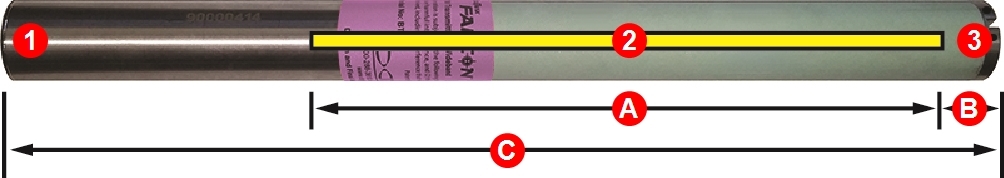
- Battery cap
- Slot position
- Front end cap
A. Slot length
B. Slot position
C. Transmitter length
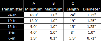
While a Falcon transmitter is compatible with older housing slot dimensions, optimal performance requires the A and B measurements shown above.
Description: Falcon F5+ 24-inch wideband, extended long-range transmitter
Product ID: FT5XLp
Model number: BTPL
Label color: Violet / blue tube
Features
- Wideband
- V2 (Multipower)
- Extended depth/data range
- Fluid pressure
- FTA battery adapter compatible
- SnooZe mode (optional)
- Made in USA
Compatible Falcon locators: F5+, F5
Transmitting frequencies: 9 bands 1,000+ from 4.5-45 kHz
Length/diameter: 24 in/1.25 in (61 cm/3.2 cm)
Clock resolution: 24
Depth/data range by power level (1) (2)
- High: up to 180 ft/220 ft (55 m/67 m)
- Standard: up to160 ft/185 ft (49 m/56 m)
- Low: up to 120 ft/140 ft (37 m/43 m)
Battery types
- Li DCI SuperCell - Double C-cell size lithium non-rechargeable 3.6v
- LiR 21700 5,000mAh - Li rechargeable 4.1v (requires a DCI FTA adapter and specific size 21700)
- Two alkaline C-cell 1.5v
Battery life by power level and battery type (2)
- High: LiR*/SuperCell Up to 8 hrs/14 hrs
- Standard: LiR*/SuperCell Up to 18 hrs/40 hrs
- Low: alkaline/LiR*/SuperCell Up to 32 hrs/44 hrs/120 hrs
- Sleep Mode: alkaline/SuperCell Up to 200 hrs/400 hrs
Pitch and fluid pressure resolution (3)
- Standard Pitch ±0.1 % at level
- Standard Pressure - 1 psi at 0–75, 5 psi at 75–250
- FSSP Pitch 0.1% from +99% to -99%
- FSSP Pressure: 5 psi at 0–50, 10 psi at 50–150, 20 psi at 150–250
Temperature readout/resolution: -4 to 219°F @ 7°F res (-20 to 104°C @ 4°C res)
Voltage/current: 1.6V - 4.2V/1.75A Max
Weight (without batteries): 2.45lb (1,111gr)
Operating environment
- Altitude: up to 6562 ft (2000 m)
- Temperature: -40 to 220°F (-40 to 104°C)
- Warranty canceled if above 220°F (104°C)
Warranty period: 3 years or 500 hours depending on which comes first. Optional extended warranty 5 years or 750 hours.
(1) Data range is based on using Falcon Max Mode.
(2) Range figures based on SAE Standard J2520. Actual ranges and battery life will vary based on interference, transmitter housing, frequency, and other factors.
(3) Standard Pitch resolution:
- 0 - 3% (0-1.7°) ±grade is 0.1% resolution;
- 3 - 9% (1.7-5.1°) is 0.2%;
- 9 - 30% (5.1-16.7°) is 0.5%;
- 30 - 50% (16.7-26.6°) is 2.0%;
- 50 - 90% (26.6-42.0°) is 5.0%
Full-Scale Sensitive Pitch (FSSP) is an F5 locator-only selectable option.
* Lithium Rechargeable battery (LiR) requires the supplied FTA battery adapter
COMPLIANCE RATINGS
This equipment complies with the following: Part 15 of the Rules of the FCC; Industry Canada license-exempt RSS standards; ACMA Radio Communications (Short Range Devices) Standard (2014). Operation is subject to the following two conditions: (1) this equipment may not cause harmful interference, and (2) this equipment must accept any interference received, including interference that may cause undesired operation.
Description: Falcon F5+ 19-inch Wideband transmitter
Product ID: FT5Lp
Model number: BTPL
Label color: Violet/blue tube
Features
- Wideband
- Long-range depth/data
- Fluid pressure
- V2 multipower
- SnooZe mode (optional)
- FTA battery adapter compatible
- Made in USA
Compatible Falcon locators: F5+, F5
Transmitting frequencies: 1,000+ from 4.5-45 kHz
Length/diameter: 19in/1.25in (48.26 cm/ 3.2 cm)
Clock resolution: 24
Depth/data range by power level (1) (2)
- High: Up to 160 ft/200 ft (49 m/61 m)
- Standard: Up to125 ft/150 ft (38 m/45.7 m)
- Low: Up to 100 ft/125 ft (30 m/38 m)
Battery types
- Li DCI SuperCell - Double C-cell size lithium non-rechargeable 3.6v
- LiR 21700 5,000mAh - Li rechargeable 4.1v (requires a DCI FTA adapter and specific size 21700)
- Two alkaline C-cell 1.5v
Battery life by power level and battery type (2)
- High: LiR*/SuperCell up to 8 hrs/14 hrs
- Standard: LiR*/SuperCell up to 18 hrs/40 hrs
- Low: alkaline/LiR*/SuperCell up to 32 hrs/44 hrs/120 hrs
- Sleep mode: alkaline/SuperCell up to 200 hrs/400 hrs
Pitch and fluid pressure resolution (3)
- Standard Pitch ±0.1 % at level
- Standard Pressure 1 psi at 0–75, 5 psi at 75–250
- FSSP Pitch 0.1% from +99% to -99%
- FSSP Pressure 5 psi at 0–50, 10 psi at 50–150, 20 psi at 150–25
Temperature readout/resolution: -4 to 219°F @ 7°F res (-20 to 104°C @ 4°C res)
Voltage/current: 1.6V - 4.2V/1.75A Max
Weight (without batteries): 2.05lb (907gr)
Operating environment
- Altitude: Up to 6562 ft (2000 m)
- Temperature: -40° to 220°F (-40 to 104°C)
- Warranty canceled if above: 220°F (104°C)
Warranty period: 3 years or 500 hours depending on which comes first. Optional extended warranty 5 years or 750 hours.
(1) Data range is based on using Falcon Max Mode.
(2) Range figures based on SAE Standard J2520. Actual ranges and battery life will vary based on interference, transmitter housing, frequency, and other factors.
(3) Standard Pitch resolution:
- 0 - 3% (0-1.7°) ±grade is 0.1% resolution;
- 3 - 9% (1.7-5.1°) is 0.2%;
- 9 - 30% (5.1-16.7°) is 0.5%;
- 30 - 50% (16.7-26.6°) is 2.0%;
- 50 - 90% (26.6-42.0°) is 5.0%
Full-Scale Sensitive Pitch (FSSP) is an F5 locator-only selectable option.
* Lithium Rechargeable battery (LiR) requires the supplied FTA battery adapter
COMPLIANCE RATINGS
This equipment complies with the following: Part 15 of the Rules of the FCC; Industry Canada license-exempt RSS standards; ACMA Radio Communications (Short Range Devices) Standard (2014). Operation is subject to the following two conditions: (1) this equipment may not cause harmful interference, and 2) this equipment must accept any interference received, including interference that may cause undesired operation.
Description: Falcon F5+ 15-inch wideband transmitter
Product ID: FT5p
Model number: BTP
Label color: Violet/blue tube
Features
- Wideband
- Long-range depth/data
- Fluid pressure
- V2 multipower
- SnooZe mode (optional)
- FTA battery adapter compatible
- Made in USA
Compatible Falcon locators: F5+, F5
Transmitting frequencies: 1000+ 4.5 - 45 kHz
Length/diameter: 15 in/1.25 in (61 cm/3.2 cm)
Clock resolution: 24
Depth/data range by power level (1) (2)
- High: up to 125 ft/160 ft (38 m/49 m)
- Standard: up to 100 ft/125 ft (30.4 m/38 m)
- Low: up to 65 ft/80 ft (20 m/ 24 m)
Battery types
- Li DCI SuperCell - Double C-cell size Lithium non-rechargeable 3.6v
- LiR 21700 5,000mAh - Li rechargeable 4.1v (requires a DCI FTA adapter and specific size 21700)
- Two Alkaline C-cell 1.5v
Battery life by power level and battery type (2)
- High: LiR*/SuperCell up to 8 hrs/14 hrs
- Standard: alkaline/LiR*/SuperCell up to 20 hrs/30 hrs/80 hrs
- Low: alkaline/LiR*/SuperCell up to 36 hrs/60 hrs/140 hrs
- Sleep Mode: alkaline/SuperCell up to 200 hrs/400 hrs
Pitch and fluid pressure resolution (3)
- Standard Pitch ±0.1 % at level
- Standard Pressure 1 psi at 0–75, 5 psi at 75–25
- FSSP Pitch 0.1% from +99% to -99%
- FSSP Pressure 5 psi at 0–50, 10 psi at 50–150, 20 psi at 150–250
Temperature readout/resolution: -4 to 219°F @ 7F res (-20 to 104°C @ 4°C res)
Voltage/current: 1.6V - 4.2V/1.75A Max
Weight (without batteries): 1.7 lb (771 gr)
Operating environment
- Altitude: Up to 6562 ft (2000 m)
- Temperature: -40 to 220°F (-40 to 104°C)
- Warranty canceled if above 220°F (104°C)
Warranty period: 3 years or 500 hours depending on which comes first. Optional extended warranty 5 years or 750 hours.
(1) Data range is based on using Falcon Max Mode.
(2) Range figures based on SAE Standard J2520. Actual ranges and battery life will vary based on interference, transmitter housing, frequency, and other factors.
(3) Standard Pitch resolution:
- 0 - 3% (0-1.7°) ±grade is 0.1% resolution;
- 3 - 9% (1.7-5.1°) is 0.2%;
- 9 - 30% (5.1-16.7°) is 0.5%;
- 30 - 50% (16.7-26.6°) is 2.0%;
- 50 - 90% (26.6-42.0°) is 5.0%
Full-Scale Sensitive Pitch (FSSP) is an F5 locator-only selectable option.
* Lithium Rechargeable battery (LiR) requires the supplied FTA battery adapter
COMPLIANCE RATINGS
This equipment complies with the following: Part 15 of the Rules of the FCC; Industry Canada license-exempt RSS standards; ACMA Radio Communications (Short Range Devices) Standard (2014). Operation is subject to the following two conditions: (1) this equipment may not cause harmful interference, and 2) this equipment must accept any interference received, including interference that may cause undesired operation.
Description: Falcon F5+ wideband 6-inch transmitter
Product ID: FT5XS
Model number: BTM
Label color: violet/blue tube
Features
- Wideband
- Short-range depth/data
- V2 multipower
- SnooZe mode (optional)
- FTA battery adapter compatible
- Made in USA
Compatible Falcon locators: F5+, F5
Transmitting frequencies: 9 Bands 1000+ frequencies 4.5 – 45 kHz
Length/diameter: 5.9 in / 0.71 in (15 cm / 1.8 cm)
Clock resolution: 24 with F5+, F5
Depth/Max Mode data (2)(3): up to 20 ft / 25 ft (7.6 m/9.1 m)
Battery types:
- Lithium DCI Supercell
- NiMH AA
- Alkaline AA
Battery life: AA alkaline/Li 1.5v: up to 17hrs/28hrs
Pitch resolutions (3)
- Standard Pitch ±0.1 % at level
- Standard Pressure 1 psi at 0–75, 5 psi at 75–25
- FSSP Pitch 0.1% from +99% to -99%
- FSSP Pressure: 5 psi at 0–50, 10 psi at 50–150, 20 psi at 150–25
Temperature readout/resolution: -4 to 220°F @ 7°F resolution (-20 to 104°C @ 4°C res)
Voltage/current: 1.0 -3.0v/400mA Max
Weight (without battery): 0.2lb (90gr)
Operating environment
- Temperature: -40 to 149°F (-40 to 65°C)
- Altitude: Up to 6562 ft (2000 m)
- Warranty canceled if above 180°F (82°C)
Warranty period: 90 Days
(1) Data Range is based on using Falcon Max Mode.
(2) Range figures based on SAE Standard J2520. Actual ranges and battery life will vary based on interference, transmitter housing, frequency, and other factors.
(3) Standard Pitch resolution
- 0 - 3% (0-1.7°) ±grade is 0.1% resolution;
- 3 - 9% (1.7-5.1°) is 0.2%;
- 9 - 30% (5.1-16.7°) is 0.5%;
- 30 - 50% (16.7-26.6°) is 2.0%;
- 50 - 90% (26.6-24.0°) is 5.0%
COMPLIANCE RATINGS
This equipment complies with the following: Part 15 of the Rules of the FCC; Industry Canada license-exempt RSS standards; ACMA Radio Communications (Short Range Devices) Standard (2014). Operation is subject to the following two conditions: (1) this equipment may not cause harmful interference, and 2) this equipment must accept any interference received, including interference that may cause undesired operation.
Description: Falcon F5+ Sub-kHz Rebar 19-inch transmitter
Product ID: FTR5Lp
Model number: BTPL
Label color: Black/blue tube
Features
- Sub-kHz rebar
- Long-range depth/data
- Fluid pressure
- Made in USA
Compatible Falcon locators: F5+, F5
Transmitting frequencies: 1000+ frequencies from 0.33 – 0.75, 4.5 – 18 kHz
Length/diameter: 19 in/1.25 in (48 cm/3.2 cm)
Clock resolution: 24
Depth/data range by power level (1) (2)
- Standard band: up to 115 ft/140 ft (35 m/43 m)
- Sub-K: up to 90 ft/115 ft (27m/ 35 m)
Battery types
- Li DCI SuperCell - Double C-cell size Lithium non-rechargeable 3.6v
- LiR 21700 5,000mAh - Li rechargeable 4.1v (requires a DCI FTA adapter and specific size 21700)
- Two Alkaline C-cell 1.5v
Battery life by power level and battery type (2)
- Standard: LiR*/SuperCell up to 18 hrs/40 hrs
- Sleep Mode: alkaline/SuperCell up to 200 hrs/400 hrs
Pitch and fluid pressure resolution (3)
- Standard Pitch ±0.1 % at level
- Standard Pressure 1 psi at 0–75, 5 psi at 75–250
- FSSP Pitch 0.1% from +99% to -99%
- FSSP Pressure 5 psi at 0–50, 10 psi at 50–150, 20 psi at 150–250
Temperature readout/resolution: -4 to 219°F @ 7°F res (-20 to 104°C @ 4°C res)
Voltage/current: 1.6V - 4.2V/1.75A Max
Weight (without batteries): 2.05lb/907gr
Operating environment
- Altitude: Up to 6562 ft (2000 m)
- Temperature: -40 to 220°F (-40 to 104°C)
- Warranty canceled if above: 220°F (104°C)
Warranty period: 3 years or 500 hours depending on which comes first. Optional extended warranty 5 years or 750 hours.
(1) Data range is based on using Falcon Max Mode.
(2) Range figures based on SAE Standard J2520. Actual ranges and battery life will vary based on interference, transmitter housing, frequency, and other factors.
(3) Standard Pitch resolution:
- 0 - 3% (0-1.7°) ±grade is 0.1% resolution;
- 3 - 9% (1.7-5.1°) is 0.2%;
- 9 - 30% (5.1-16.7°) is 0.5%;
- 30 - 50% (16.7-26.6°) is 2.0%;
- 50 - 90% (26.6-42.0°) is 5.0%
Full-Scale Sensitive Pitch (FSSP) is an F5 locator-only selectable option.
* Lithium Rechargeable battery (LiR) requires the supplied FTA battery adapter
COMPLIANCE RATINGS
This equipment complies with the following: Part 15 of the Rules of the FCC; Industry Canada license-exempt RSS standards; ACMA Radio Communications (Short Range Devices) Standard (2014). Operation is subject to the following two conditions: (1) this equipment may not cause harmful interference, and 2) this equipment must accept any interference received, including interference that may cause undesired operation.
Description: Falcon F5+ 15-inch Sub-kHz Rebar
Product ID: FTR5p
Model number: BTP
Label color: Black/blue tube
Features
- Sub-kHz rebar
- Long-range depth/data
- Fluid pressure
- FTA battery adapter compatible
- Made in USA
Compatible Falcon locators: F5+, F5
Transmitting frequencies: 1,000+ from 4.5-45 kHz
Length/diameter: 15in/1.25 in (61 cm/3.2 cm)
Clock resolution: 24
Depth/data range by power level (1) (2)
- Standard: Up to 90 ft/115 ft (27 m/35 m)
- Sub-K: Up to 60 ft/80 ft (18 m/ 24 m)
Battery types
- Li DCI SuperCell - Double C-cell size lithium non-rechargeable 3.6v
- LiR 21700 5,000mAh - Li rechargeable 4.1v (requires a DCI FTA adapter and specific size 21700)
- Two-alkaline C-cell 1.5v
Battery life by power level and battery type (2)
- Standard: alkaline/LiR*/SuperCell Up to 20 hrs/30 hrs/80 hrs
- Sleep Mode: alkaline/SuperCell Up to 200 hrs/400 hrs
Pitch and fluid pressure resolution (3)
- Standard Pitch ±0.1 % at level
- Standard Pressure 1 psi at 0–75, 5 psi at 75–250
- FSSP Pitch 0.1% from +99% to -99%
- FSSP Pressure 5 psi at 0–50, 10 psi at 50–150, 20 psi at 150–250
Temperature readout/resolution: -4 to 219°F @ 7F res (-20 to 104°C @ 4°C res)
Voltage/current: 1.6V - 4.2V/1.75A Max
Weight (without batteries): 1.7lb/771gr
Operating environment
- Altitude: Up to 6562 ft (2000 m)
- Temperature: -40° to 220°F (-40 to 104°C)
- Warranty canceled if above: 220°F (104°C)
Warranty period: 3 years or 500 hours depending on which comes first. Optional extended warranty 5 years or 750 hours.
(1) Data range is based on using Falcon Max Mode.
(2) Range figures based on SAE Standard J2520. Actual ranges and battery life will vary based on interference, transmitter housing, frequency, and other factors.
(3) Standard Pitch resolution:
- 0 - 3% (0-1.7°) ±grade is 0.1% resolution;
- 3 - 9% (1.7-5.1°) is 0.2%;
- 9 - 30% (5.1-16.7°) is 0.5%;
- 30 - 50% (16.7-26.6°) is 2.0%;
- 50 - 90% (26.6-42.0°) is 5.0%
Full-Scale Sensitive Pitch (FSSP) is an F5 locator-only selectable option.
* Lithium Rechargeable battery (LiR) requires the supplied FTA battery adapter
COMPLIANCE RATINGS
This equipment complies with the following: Part 15 of the Rules of the FCC; Industry Canada license-exempt RSS standards; ACMA Radio Communications (Short Range Devices) Standard (2014). Operation is subject to the following two conditions: (1) this equipment may not cause harmful interference, and (2) this equipment must accept any interference received, including interference that may cause undesired operation.
Description: Falcon F5+ 8-inch Sub-kHz Rebar transmitter
Product ID: FTR5S
Model number: BTS
Label color: Black/blue tube
Features
- Sub-kHz Rebar
- Fluid pressure
- Made in USA
Compatible Falcon locators: F5+, F5
Transmitting frequencies: 6 bands/450+ frequencies 0.33 – 0.75, 4.5 – 18 kHz
Length/diameter: 8 in/1.0 in (20.3 cm / 2.5 cm)
Clock resolution: 24
Depth/data range by power level (2) (3)
- Standard: up to 25 ft / 25 ft (7.6 m/7.6 m)
- Down band (Sub-K mode): up to 20 ft/20 ft (6 m/6 m)
Battery type: 123 3V lithium
Battery life
- Standard: up to 16 hrs
- Sleep mode: up to 150 hrs
Pitch and pressure resolution (3)
- Standard Pitch ±0.1 % at level
- Standard Pressure 1 psi at 0–75, 5 psi at 75–25
- FSSP Pitch 0.1% from +99% to -99%
- FSSP Pressure 5 psi at 0–50, 10 psi at 50–150, 20 psi at 150–25
Temperature readout/resolution: -4 to 219°F @ 7°F res (-20 to 104°C @ 4°C res)
Voltage/current: 1.0 -3.0v/400mA Max
Weight (without batteries): 0.6 lb (272 g)
Operating environment
- Altitude: Up to 6562 ft (2000 m)
- Temperature: -40 to 220°F (-40 to 104°C)
- Warranty canceled if above: 180°F (82°C)
Warranty period: 90 Days
(1) Data range is based on using Falcon Max Mode.
(2) Range figures based on SAE Standard J2520. Actual ranges and battery life will vary based on interference, transmitter housing, frequency, and other factors.
(3) Standard Pitch resolution:
- 0 - 3% (0-1.7°) ±grade is 0.1% resolution;
- 3 - 9% (1.7-5.1°) is 0.2%;
- 9 - 30% (5.1-16.7°) is 0.5%;
- 30 - 50% (16.7-26.6°) is 2.0%;
- 50 - 90% (26.6-42.0°) is 5.0%.
COMPLIANCE RATINGS
This equipment complies with the following: Part 15 of the Rules of the FCC; Industry Canada license-exempt RSS standards; ACMA Radio Communications (Short Range Devices) Standard (2014). Operation is subject to the following two conditions: (1) this equipment may not cause harmful interference, and 2) this equipment must accept any interference received, including interference that may cause undesired operation.
Description: Falcon F2+ V2 19-inch wideband long-range
Product ID: FT2L+
Model number: BTWL
Label color: Lavender/blue tube
Features
- Wideband
- Extended depth/data range
- V2 multipower
- Expanded pitch range (1)
- FTA battery adapter compatible
- Made in USA
Compatible Falcon locators: F5+, F2+
Transmitting frequencies: 9 bands 550+ frequencies from 4.5-45 kHz
Length/diameter: 19in/1.25in (48.26cm/3.2cm)
Clock resolution: 24
Depth/Max Mode data range by power level (2)(3)
- High: 160ft/200ft (49m/61m)
- Standard: 125ft/150ft (38m/45.7m)
- Low: 100ft/125ft (30m/38m)
Battery types
- Li DCI Supercell - Double C-cell size Lithium non-rechargeable 3.6v
- LiR 21700 5,000mAh - Li rechargeable 4.1v (requires a DCI FTA adapter and specific size 21700)
- Two alkaline C-cell 1.5v
Battery life by power level and battery type (2)
- High: LiR*/SuperCell: 8 hrs/14 hrs
- Standard: LiR*/SuperCell: 18 hrs/40 hrs
- Low: alkaline/LiR*/SuperCell: 32hrs/44hrs/120hrs
- Sleep mode, alkaline/SuperCell 200hrs/400hr
Pitch resolution (1)
- Standard mode ±0.1 % at level decreasing with increased pitch
- Expanded mode (F2+ Locators only) 1.0% to maximum expanded pitch ±99% (44.7°) or ±119% (50.0°) based on transmitter and locator software).
Temperature readout/resolution: -4 to 219°F @ 7°F res (-20 to 104°C @ 4°C res)
Voltage/current: 1.6V - 4.2V/1.75A Max
Weight (without batteries): 2.05lb/907g
Operating environment
- Altitude: Up to 6562 ft (2000 m)
- Temperature: -40 to 149°F (-40 to 65°C)
- Warranty canceled if above: 220°F (104°C)
Warranty period: 3 years/500 hours (5 years/750 hours optional extended warranty)
(1) Standard Pitch resolution:
- 0 - 3% (0-1.7°) ±grade is 0.1% resolution;
- 3 - 9% (1.7-5.1°) is 0.2%;
- 9 - 30% (5.1-16.7°) is 0.5%;
- 30 - 50% (16.7-26.6°) is 2.0%;
- 50 - 90% (26.6-42.0°) is 5.0%
Expanded pitch resolution (with Falcon F2+ only)
When this model transmitter is paired with a Falcon F2+ locator manufactured after May 5, 2025 with software version 6000-5122-1030-6250R or later, the maximum expanded pitch range may vary depending on the transmitter's software and manufactured date.
- 0% - ±99% (44.7°) is 1.0% (Transmitters manufactured 2017 to mid-2025)
- 0% up to ±119% (50.0°) is 1.0% (Transmitters manufactured mid-2025 software version 2.1.9.0 or later)
Search the DCI DigiGuide App for details and instructions.
(2) Data range is based on using Falcon Max Mode.
(3) Range figures based on SAE Standard J2520. Actual ranges and battery life will vary based on interference, transmitter housing, frequency, and other factors.
* Lithium Rechargeable battery (LiR) requires the supplied FTA battery adapter.
COMPLIANCE RATINGS
This equipment complies with the following: Part 15 of the Rules of the FCC; Industry Canada license-exempt RSS standards; ACMA Radio Communications (Short Range Devices) Standard (2014). Operation is subject to the following two conditions: (1) this equipment may not cause harmful interference, and 2) this equipment must accept any interference received, including interference that may cause undesired operation.
Description: FT2 Falcon F2+ 15-in wideband transmitter
Product ID: FT2 V2
Model number: BTW
Label color: Red/blue tube
Features
- Wideband
- V2 multipower
- Expanded pitch range (1)
- FTA battery adapter compatible
- Made in USA
Compatible Falcon locators: F5+, F5, F2+, F2
Transmitting frequencies: 9 Bands 1000+ frequencies 4.5 – 45 kHz
Length/diameter: 15in / 1.25 in (38.1 cm / 3.2c m)
Clock resolution: 24 with F2+ / F5+ and 12 with F2 / F5
Depth and data range by power level (2)(3)
- High: up to 125 ft/160 ft (38 m/49 m)
- Standard: up to 100 ft/125 ft (30.4 m/38 m)
- Low: up to 65 ft/80 ft (20 m/ 24 m)
Battery types
- Li DCI SuperCell - Double C-cell size lithium non-rechargeable 3.6v
- LiR 21700 5,000mAh - Li rechargeable 4.1v (requires a DCI FTA adapter and specific size 21700)
- Two alkaline C-cell 1.5v (low/standard power only)
Battery life by power level and battery type (3)
- High: LiR*/SuperCell: up to 8 hrs/14 hrs
- Standard: alkaline/LiR*/SuperCell: up to 20 hrs/30 hrs/80 hrs
- Low: alkaline/LiR*/SuperCell: up to 36 hrs/60 hrs/140 hrs
- Sleep Mode: alkaline/SuperCell: up to 200 hrs/400 hrs
Pitch resolution (1)
- Standard mode ±0.1 % at level decreasing with increased pitch
- Expanded mode (F2+ Locators only) 1.0% to maximum expanded pitch ±99% (44.7°) or ±119% (50.0°) based on transmitter and locator software).
Temperature readout/resolution: -4 to 219°F @ 7°F res (-20 to 104°C @ 4°C res)
Voltage/current: 1.6V - 4.2V/1.75A Max
Weight (without batteries): 1.7lb (771g)
Operating environment
- Altitude: up to 6562 ft (2000 m)
- Temperature: -40 to 149°F (-40 to 65°C)
- Warranty canceled if above: 220°F (104°C)
Warranty period: 3 years/500 hours (5 years/750 hours optional extended warranty)
(1) Standard Pitch resolution:
- 0 - 3% (0-1.7°) ±grade is 0.1% resolution;
- 3 - 9% (1.7-5.1°) is 0.2%;
- 9 - 30% (5.1-16.7°) is 0.5%;
- 30 - 50% (16.7-26.6°) is 2.0%;
- 50 - 90% (26.6-42.0°) is 5.0%
Expanded pitch resolution (with Falcon F2+ only)
When this model transmitter is paired with a Falcon F2+ locator manufactured after May 5, 2025 with software version 6000-5122-1030-6250R or later, the maximum expanded pitch range may vary depending on the transmitter's software and manufactured date.
- 0% - ±99% (44.7°) is 1.0% (Transmitters manufactured 2017 to mid-2025)
- 0% up to ±119% (50.0°) is 1.0% (Transmitters manufactured mid-2025 software version 2.1.9.0 or later)
Search the DCI DigiGuide App for details and instructions.
(2) Data range is based on using Falcon Max Mode.
(3) Range figures based on SAE Standard J2520. Actual ranges and battery life will vary based on interference, transmitter housing, frequency, and other factors.
* Lithium Rechargeable battery (LiR) requires the supplied FTA battery adapter
COMPLIANCE RATINGS
This equipment complies with the following: Part 15 of the Rules of the FCC; Industry Canada license-exempt RSS standards; ACMA Radio Communications (Short Range Devices) Standard (2014). Operation is subject to the following two conditions: (1) this equipment may not cause harmful interference, and 2) this equipment must accept any interference received, including interference that may cause undesired operation.
Description: Falcon F2+ V2 8-inch wideband short-range transmitter
Product ID: FT2S
Model number: BTS
Label color: red/blue tube
Feature
- Wideband
- Short-range depth/data
- V2 multipower
- Expanded pitch range (1)
- Made in USA
Compatible Falcon locators: F5+, F5, F2+, F2
Transmitting frequencies: 9 Bands 500+ frequencies 4.5 – 45 kHz
Length/diameter: 8in/1.0in (20.3 cm/2.5 cm)
Clock resolution: 24 with F+ and 12 with F5, F2 locators
Depth and Max Mode data range by power level (2)(3)(4)
- High: up to 50 ft/50 ft (15.2 m/15.2 m)
- Standard: up to 40 ft/40 ft (12.2 m/12.2 m)
- Low: up to 25 ft/25 ft (7.6 m/7.6 m)
Battery types: Li 123 cell
Battery life by power level and battery type
- High: up to 12 hrs
- Standard: up to 16 hrs
- Low: up to 18 hrs
- Sleep mode: up to 150 hrs
Pitch resolution (1)
- Standard mode ±0.1 % at level decreasing with increased pitch
- Expanded mode (F2+ Locators only) 1.0% to maximum expanded pitch ±99% (44.7°) or ±119% (50.0°) based on transmitter and locator software).
Temperature readout/resolution: -4 to 220°F @ 7°F resolution (-20 to 104°C @ 4°C res)
Voltage/current: 1.0 -3.0v/400mA Max
Weight without batteries: 1.7lb/771gr
Operating environment
- Temperature: -40 to 180°F (-40 to 65°C)
- Altitude: up to 6562 ft (2000 m)
- Warranty canceled if above 180ºF (82ºC)
Warranty period: 90 Days
(1) Standard Pitch resolution:
- 0 - 3% (0-1.7°) ±grade is 0.1% resolution;
- 3 - 9% (1.7-5.1°) is 0.2%;
- 9 - 30% (5.1-16.7°) is 0.5%;
- 30 - 50% (16.7-26.6°) is 2.0%;
- 50 - 90% (26.6-42.0°) is 5.0%
Expanded pitch resolution (with Falcon F2+ only)
When this model transmitter is paired with a Falcon F2+ locator manufactured after May 5, 2025 with software version 6000-5122-1030-6250R or later, the maximum expanded pitch range may vary depending on the transmitter's software and manufactured date.
- 0% - ±99% (44.7°) is 1.0% (Transmitters manufactured 2017 to mid-2025)
- 0% up to ±119% (50.0°) is 1.0% (Transmitters manufactured mid-2025 software version 2.1.9.0 or later)
(2) Data Range is based on using Falcon Max Mode.
(3) Range figures based on SAE Standard J2520. Actual ranges and battery life will vary based on interference, transmitter housing, frequency, and other factors.
(4) V2 Low power has faster data with Falcon 1.1 QSP Software
COMPLIANCE RATINGS
This equipment complies with the following: Part 15 of the Rules of the FCC; Industry Canada license-exempt RSS standards; ACMA Radio Communications (Short Range Devices) Standard (2014). Operation is subject to the following two conditions: (1) this equipment may not cause harmful interference, and (2) this equipment must accept any interference received, including interference that may cause undesired operation.
Depth Increase in Inches (cm)
| % slope | Depth increase cm | % slope | Depth increase cm |
|---|---|---|---|
| 1 | 2 | 14 | 43 |
| 2 | 5 | 15 | 46 |
| 3 | 10 | 16 | 48 |
| 4 | 13 | 17 | 51 |
| 5 | 15 | 18 | 53 |
| 6 | 18 | 19 | 56 |
| 7 | 20 | 20 | 61 |
| 8 | 25 | 21 | 64 |
| 9 | 28 | 22 | 66 |
| 10 | 30 | 23 | 69 |
| 11 | 33 | 24 | 71 |
| 12 | 36 | 25 | 74 |
| 13 | 36 | 26 | 76 |
| % slope | Depth increase cm | % slope | Depth increase cm |
|---|---|---|---|
| 27 | 79 | 41 | 117 |
| 28 | 81 | 42 | 117 |
| 29 | 84 | 43 | 119 |
| 30 | 86 | 44 | 122 |
| 31 | 91 | 45 | 124 |
| 32 | 94 | 46 | 127 |
| 33 | 97 | 47 | 130 |
| 34 | 99 | 50 | 137 |
| 35 | 102 | 55 | 147 |
| 36 | 104 | 60 | 157 |
| 37 | 107 | 70 | 175 |
| 38 | 109 | 80 | 191 |
| 39 | 112 | 90 | 203 |
| 40 | 114 | 100 | 216 |
Slopes between 50% and 100% are provided for reference only and do not represent typical drilling conditions. All numbers are based on math only and do not take into account extremely soft or extremely hard soil conditions, which may cause depth values to vary.
Depth Increase in Inches (cm)
| % slope | Depth increase cm | % slope | Depth increase cm | % slope | Depth increase cm |
|---|---|---|---|---|---|
| 1 | 2 | 19 | 56 | 37 | 107 |
| 2 | 5 | 20 | 61 | 38 | 109 |
| 3 | 10 | 21 | 64 | 39 | 112 |
| 4 | 13 | 22 | 66 | 40 | 114 |
| 5 | 15 | 23 | 69 | 41 | 117 |
| 6 | 18 | 24 | 71 | 42 | 117 |
| 7 | 20 | 25 | 74 | 43 | 119 |
| 8 | 25 | 26 | 76 | 44 | 122 |
| 9 | 28 | 27 | 79 | 45 | 124 |
| 10 | 30 | 28 | 81 | 46 | 127 |
| 11 | 33 | 29 | 84 | 47 | 130 |
| 12 | 36 | 30 | 86 | 50 | 137 |
| 13 | 36 | 31 | 91 | 55 | 147 |
| 14 | 43 | 32 | 94 | 60 | 157 |
| 15 | 46 | 33 | 97 | 70 | 175 |
| 16 | 48 | 34 | 99 | 80 | 191 |
| 17 | 51 | 35 | 102 | 90 | 203 |
| 18 | 53 | 36 | 104 | 100 | 216 |
Slopes between 50% and 100% are provided for reference only and do not represent typical drilling conditions. All numbers are based on math only and do not take into account extremely soft or extremely hard soil conditions, which may cause depth values to vary.
Depth Increase in Inches (cm)
| % slope | Depth increase cm | % slope | Depth increase cm | % slope | Depth increase cm |
|---|---|---|---|---|---|
| 1 | 5 | 19 | 86 | 37 | 157 |
| 2 | 10 | 20 | 89 | 38 | 163 |
| 3 | 13 | 21 | 94 | 39 | 165 |
| 4 | 18 | 22 | 99 | 40 | 170 |
| 5 | 23 | 23 | 102 | 41 | 173 |
| 6 | 28 | 24 | 107 | 42 | 178 |
| 7 | 33 | 25 | 112 | 43 | 180 |
| 8 | 36 | 26 | 114 | 44 | 183 |
| 9 | 41 | 27 | 19 | 45 | 188 |
| 10 | 46 | 28 | 124 | 46 | 191 |
| 11 | 51 | 29 | 127 | 47 | 196 |
| 12 | 53 | 30 | 132 | 50 | 203 |
| 13 | 58 | 31 | 135 | 55 | 221 |
| 14 | 64 | 32 | 140 | 60 | 236 |
| 15 | 69 | 33 | 142 | 70 | 262 |
| 16 | 71 | 34 | 147 | 80 | 284 |
| 17 | 76 | 35 | 150 | 90 | 305 |
| 18 | 81 | 36 | 155 | 100 | 323 |
Slopes between 50% and 100% are provided for reference only and do not represent typical drilling conditions. All numbers are based on math only and do not take into account extremely soft or extremely hard soil conditions, which may cause depth values to vary.
If you know the transmitter pitch, the positions of the front locate point (FLP) and the rear locate point (RLP), and if the ground surface is level, you can still estimate the transmitter depth even if the depth information displayed on the locator becomes unreliable.
To estimate the transmitter depth, first measure the distance between the FLP and the RLP. The pitch of the transmitter must also be reliably known. Using the Depth Estimation Table below, find the divider that most closely corresponds to the transmitter pitch. Then use the following formula to estimate the depth:
Depth = Distance between FLP and RLP / Divider
For example, if the transmitter pitch is 34% (or 18.8°) then the corresponding divider value (from the table) is 1.50.
In this example, the distance between the FLP and the RLP is 11.5 ft. The depth would be:
Depth = 11.5 ft. / 1.50 = 7.66 ft.
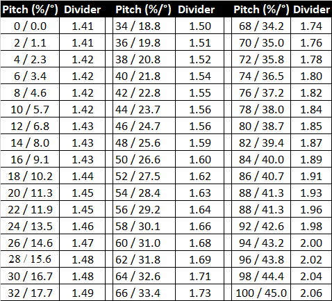
Standard resolution:
- from 0–75 psi is 1 psi
- from 75–250 psi is 5 psi
Resolution after selecting Transmitter pairing request 0.1% / 100% (Full Scale Sensitive Pitch, FSSP) for a compatible Falcon F5 or F5+transmitter:
- from 0–50 psi is 5 psi
- from 50–150 psi is 10 psi
- from 150–250 psi is 20 psi
Resolution at:
- 0 – 3% grade (0 – 1.7°) is 0.1%
- 3 – 9% grade (1.7 – 5.1°) is 0.2%
- 9 – 30% grade (5.1 – 16.7°) is 0.5%
- 30 – 50% grade (16.7 – 26.6°) is 2.0%
- 50 – 90% grade (26.6 – 42.0°) is 5.0%
Watch a selection of training videos or go to the full library of DigiTrak training videos at www.Youtube.com/DCIKent.
Some videos are only available in English. If needed, please turn on subtitles and automatic translations.
Watch video on YouTube:
DigiTrak - Falcon F5 with Sub-K Rebar transmitter animated demonstration (2:19 min)
Watch video on YouTube:
Calibrate Your DCI Transmitter and Locator (1:52 min)
Contact
DCI USA
19625 62nd Ave S, Suite B103
Kent, WA USA 98032
DCI@digital-control.com
1.800.288.3610
1.425.251.0559
DCI Australia
2/9 Frinton Street Southport
Queensland 4215 Australia
DCI.Australia@digital-control.com
+61.7.5531.4283
+61.7.5531.2617
DCI China
368 Xingle Road Huacao Town
Minhang District Shanghai 201107, P.R.C
DCI.China@digital-control.com
+86.400.100.8708
+86.21.6432.5186
DCI Europe
Brueckenstraße 2
97828 Marktheidenfeld Germany
DCI.Europe@digital-control.com
+49.9391.810.6100
+49.9391.810.6109
DCI India
Unit No. 1022, 10th Floor DLF Tower B Jasola District Center
New Delhi 110025 India
DCI.India@digital-control.com
+91.11.4507.0444
+91.11.4507.0440
DCI Philippines
404-405 Energy Opt. Bldg Prime St, Madrigal Business Park 2
Alabang Muntinlupa City, Philippines 1780
DCI.Philippines@digital-control.com
(02)79802647
+632-79802647