TeraTrak® R1 User Manual
DCI DigiGuide 2026.03.13
DCI DigiGuide User Manual
2026.03.13
All operators must read and understand this operator’s guide before using their TeraTrak. Should the equipment be used in a manner not specified in the operator’s guide, the protection provided by the equipment may be impaired.
Failure to properly care for and maintain your TeraTrak may result in malfunction or inoperability of the unit. If your TeraTrak malfunctions or ceases to operate for any reason, stop usage immediately and contact DCI Customer Service.
The precision of TeraTrak R1 data depends on maintaining as much contact between the crown of R1's tires and the ground surface as possible at all times during operation. Losing ground contact for even a moment can reduce the accuracy of R1 measurements. Ensure wheels are free of debris. Walking speed and bumpiness of the surface can reduce wheel contact with the ground.
Follow the Dynamic Speed Gauge carefully and minimize "red zone" readings while using R1. Don't use R1 on snow or sand and walk particularly slowly over cobble. Also take care to proceed slowly over curbs. Keep R1 upright while operating, do not tilt to a side.
Since R1 is designed to produce precision measurements, it is critical that all inputs be as precise as possible. Inaccurate input data will impact the accuracy of R1 output.
The foregoing factors, failure to carefully follow the operating instructions, as well as other factors may reduce the accuracy of R1 data. Imprecise R1 data can lead to inaccurate positioning of the drill rig and inaccuracies in your bore planning.
Inaccuracies in your bore planning can lead to striking underground utilities, inaccurate installations and/or lost time. You must continue following customary safety protocols at the jobsite, including identifying buried utilities and maintaining a customary safety buffer.
Do not rely solely on R1 data. DCI strongly recommends matching up DCI locating system measurements against R1 data points to ensure alignment.
System working elevation: up to 6500 ft (1981.2 m)
Operating temperatures:
- Run mode: -4°F to 140° F (-20°C to 60°C)
- Charge mode: 32°F to 104°F (0°C to 40°C)
- Storage and transportation: -40°F to 149°F (-40°C to 65°C)
Relative Humidity: <90%
Dust and Water Ingress: IP65 per IEC 60529
Handling Drop (1 meter): IEC 61010
Vibration: MIL-STD-810G
Electrostatic Discharge: IEC 61000-4-2
Operation may be compromised if the equipment is subjected to conditions outside these specified limits.
Ship in original carrying case or packaging of sufficient durability to prevent mechanical shock to equipment during transportation.
If you have any questions about the operation of your TeraTrak R1 App or R1, please contact DCI Customer Service for assistance.
Disposal
This equipment must adhere to the WEEE Recast Directive (2012/19/EU) and cannot be disposed of with household waste. For more information about how to properly dispose of this equipment, contact our customer service department.
The TeraTrak R1 lets you gather data about the terrain and elevation changes of your job site in real-time. The R1 connects via Bluetooth to the TeraTrak R1 App installed on your mobile device.
In the App, you can mark utilities and define reference points, called waypoints, while walking the bore path. TeraTrak also generates maps, charts, and rod-by-rod bore plans.
The collected terrain data and job site data can be used for bore planning in the application of your choice.
The R1 uses multi-axis sensors to measure the angle between the two wheels. These sensors are a key reason the R1 is able to chart terrain precisely. As it travels over the terrain it continually collects angle and distance data which the algorithms turn into elevation data.
As you work with longer paths (greater than 125 ft), small errors in the elevation measurements can accumulate. By following the same path back to the original starting point, many of the accumulated errors can be averaged out by the compensation algorithm.
However, a drawback with the multi-axis sensors is that with precision it is also more sensitive to fast movements. When a user goes over bumpy terrain the user introduces fast movements (shock) that are difficult to filter out. Following the speed gauge * will ensure the most accurate data collection.
For more information on gathering better data, see "Collecting the Best Data" in the Bootcamp chapter.
The terrain and distance data are referenced from the starting point (or the entry point if it has been moved), which is set initially as distance=0 and elevation=0. For example, distance= 80 ft 0 in and elevation= -22 ft 1 in, the point being measured is the distance and elevation from the starting point.
TeraTrak R1 speed gauge displays while the R1 is gathering data and provides feedback on optimum speed for data gathering. The indicator must be in the green zone for the most accurate data.
- Mobile device holder
- Handle adjustment
- Battery strength and Bluetooth indicator
- Charging plug outlet
- Kickstand
- Reference point
- Keep a steady pace with both wheels on the ground, rotating smoothly and without bouncing. You may need to go slower than the speed gauge * suggests to ensure accurate readings over bumpy ground. If measurements are taken while the gauge is in the red area, data may be suspect.
- Mark the ground where you start gathering data and at every mark made in the TeraTrak R1 App. The reference point * is the center point between the wheels where the handle is attached.
- To ensure accuracy of the data, always walk the return path as closely as possible to the original. The return path is shown in orange and then changes back to green after the two paths are compared and determined to be accurate.
- If the forward and return path are too dissimilar, the R1 App cannot combine the two paths. A message will advise you to rewalk the path to gather additional data.
TeraTrak R1 speed gauge displays while the R1 is gathering data and provides feedback on optimum speed for data gathering. The indicator must be in the green zone for the most accurate data.
This is the spot on the R1 that is used as a reference for the data gathered by the R1. It is the center point between the wheels where the handle is attached. See the "Parts of the TeraTrak R1" in the Bootcamp Chapter for an illustration.
There are a few key factors to consider when creating a bore plan using the TeraTrak R1 app. The R1 bore planning algorithms were developed to drill as many rods straight as possible. This increases productivity since generally drilled rods take less time than rods that need steering. The location and number of waypoints * play an important role in creating the bore plan.
Drill parameters
You can set drill parameters for your typical jobs in the R1 App. Go to the Drill Parameters section in Settings to set your rod lengths, max bend per rod, entry angle, and depth, as well as the exit angle and depth. You can also change the drill parameters for individual jobs. For example, if you typically plan for a 10 ft (3 m) rod machine but need a bore plan for a 15 ft (4.5 m) rod drill, you can change the rod length for just that specific job.
Collecting terrain data
It is important to mark the point where you started collecting data. Maintaining a walking speed that keeps the R1 speed indicator * in the optimum green zone provides the most accurate survey of the terrain.
It is also very important that the return path follows the outbound path as closely as possible and ends at the same spot where the outbound path started collecting data.
A best practice is to gather extra terrain data (20 to 30 ft (6 to 9 m) on both ends so that the entry and exit can be moved if needed.
Placing waypoints
A waypoint is a point in the bore plan that the bore path must travel through. It is a best practice to have only a few strategically placed waypoints. An appropriate waypoint is a depth requirement below the bottom of a creek or a roadway. The more waypoints in a bore plan, the more restrictive the solutions become, and the more difficult it is to achieve a valid bore path.
Specifying a Pitch
The second element of a waypoint is the option of a desired pitch or manually adding it. In addition to the depth and placement, you can enter a pitch, 0% as an example. The more waypoints with manual pitch that are added, the more difficult it may be to create a valid bore plan. So, unless necessary, it is better to use the Auto selection and let the app calculate the pitch for you.
In cases of an invalid plan, where you have a manual pitch entry at a waypoint, it could be worthwhile to use Auto pitch to get to a valid plan and then see if the auto-calculated pitch is acceptable. If that does not get you to a valid plan, moving and potentially removing waypoints are the next steps.
Valid bore paths
A valid bore path is not overbent, based on the max bend per rod, and does not encroach on a utility clearance.
A valid bore path is displayed as a solid blue line in the R1 app.
An invalid bore path is displayed as a red dotted line. The red waypoints in the grid and the red entries in the chart indicates waypoints that need attention.
Use the TeraTrak R1 App to start, stop, pause, and add markers to charts as you gather data. After the data is collected, there are additional controls to measure and evaluate the charts. Some controls are only available when the App is connected to the R1, or while actively collecting and working with data.
In this guide, screenshots come from both Android and iOS devices. Some buttons and screens may appear differently than on your device.
The R1 App allows the user to choose to display depth readings two ways: Locator Depth and Depth Below Terrain.
Locator Depth matches the depth the DigiTrak locator displays on the Locate Mode screen. R1 boreplans display depth readings that uniquely match the DCI locator's display. Use Locator Depth to ensure that your R1 boreplans match the expected depth readings from a DCI locator.
Depth Below Terrain is the vertical depth to the drill head from the terrain. This measurement is useful with non-DCI equipment. This could be a physically measured depth. For example, taken with a tape measure.
These controls appear on the top of the TeraTrak R1 App screens.
Back - Returns to the previous screen
Export - Exports charts as CSV * and PDF * files
Devices - Paired and discovered R1s
Delete - Delete a job
Edit - Edit job information
"Comma-separated value" is a plain text file that stores data. Each line of the file is a data record with fields separated into columns with commas. The CSV file is used by applications to export and import data.
"Portable Document File" - PDF stands for "portable document format". PDF files cannot be modified.
Use these buttons to control the collection of data. Some controls only appear when you are connected to an R1 and actively collecting data.
Pause Job - Pause recording while data gathering.
Start/Resume Job - Start or resume data gathering.
Return path - Walk the same path in the opposite direction to validate measurements.
Finish Job - Complete the job.
Add Markers - After Pausing, add markers to the chart. See "Add Markers for Utilities and Waypoints" in the Collect Data chapter.
Quick Add - Only available while collecting data. Adds a generic marker, which can be edited later, and restarts collecting data automatically.
There are four kinds of jobs that display terrain information. Choose the type of job before you begin collecting data: Standard Terrain, Two-Point Calculation, Setback Calculation, and Distance Measurement.
Use the Standard Terrain Job to survey a job site and create complete bore plans. The chart displays distances, elevations, and pitch.
When using R1 to determine where to set your rig, the Setback Calculation helps you calculate where to set your drill rig to reach a specific depth and pitch.
When planning a drill path between two points, the Two-Point Calculation uses the terrain, waypoints, and utilities you've marked to give you a rod-by-rod plan.
When measuring terrain distance, use the Distance Measurement.
Use the TeraTrak R1 App to start, stop, pause, and add markers to the chart to indicate utilities and other important features.
In this guide, screenshots come from both Android and iOS devices. Some buttons and screens may appear differently than on your device.
Watch video on YouTube:
Stuff You Should Know

These controls appear on the side and bottom of the TeraTrak R1 App screens and are only available after you have finished a job. They allow you to measure and calculate distances and pitch from the chart, display tables, and change the chart.
Table - Calculate and display the Rod by Rod table.
Pitch Calculation - Calculates the average pitch between two waypoints, as well as depth difference.
Measurement Mode - Measures surface distance, horizontal distance, elevation difference, and pitch between two points on the terrain.
Add Markers - Add waypoints, utilities, and other markers.
Scaling - Choose how the chart is scaled in the R1 app and in PDFs.
Chart - Toggle between chart and bird's eye view.
Map - Toggle between bird's eye view map and chart.
You can use the pinch and spread controls to zoom in or zoom out of data, maps, and charts.
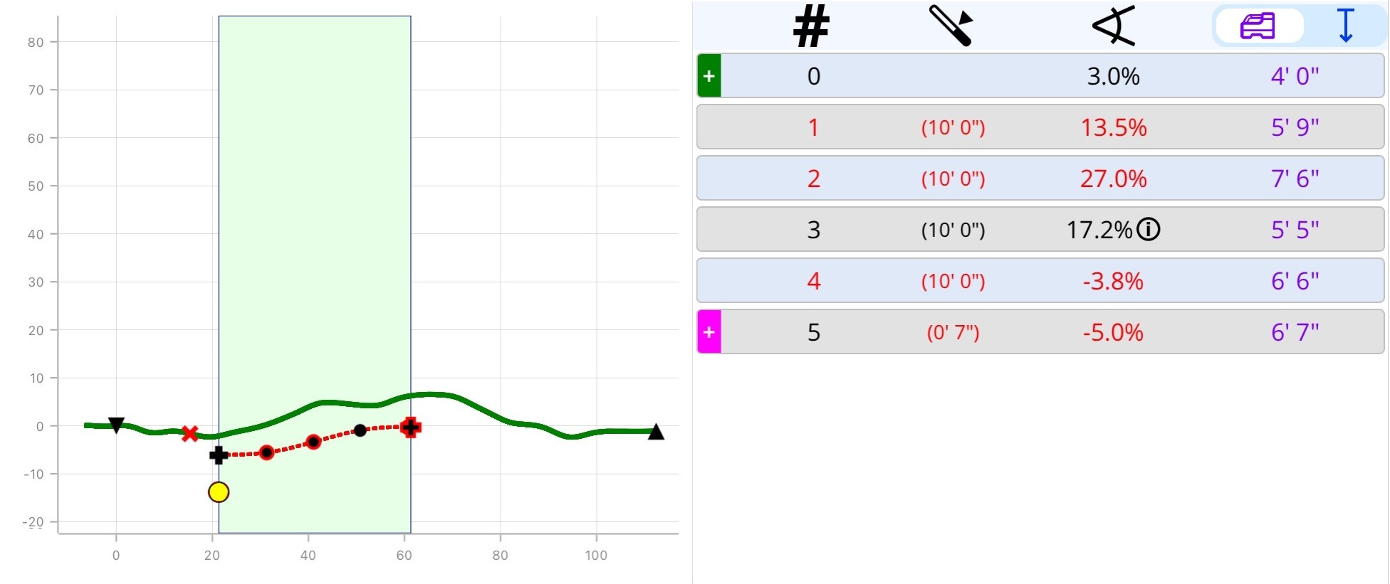
The rod-by-rod table is available for Standard, Setback, and Two-Point Calculation job types. After you finish mapping, tap Table.
A rod-by-rod plan is generated based on your default settings and the data collected.
Tap a dot on the bore path to highlight the corresponding row of data.
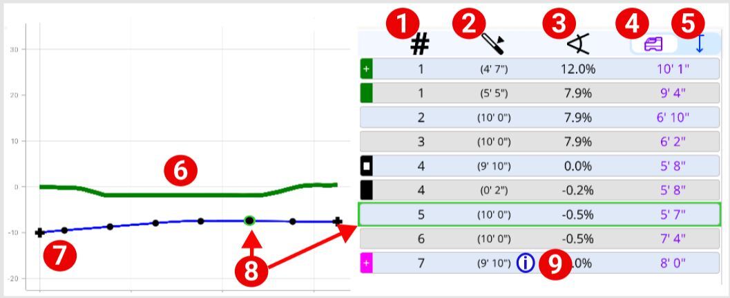
- Rod number
- Rod length or rod remaining
- Pitch
- Locator depth
- Vertical depth
- Terrain topography
- Entry point (for Setback job) or current starting point
- Rod and corresponding rod data
- More information is available on this data point. See "App Messages" in the Advanced Topics chapter.
You can toggle between a chart view and a bird eye's view.
Pin - Start position
Orange pin - End position
White dot - Current position (not shown)
To add a pin - Use the current location or tap on the map for position
Display options - Toggle on and off, Start, End, and Current Position
The App uses the native map software for your device's operating system, Apple Maps or Google maps. Map markings may differ.
Insert the handle into the socket until it locks in place.
Use the buttons on the bottom to adjust the handle to a comfortable height.
Attach the mobile device holder.
Plug the charger cable into the R1 charging port, then into the power brick. Plug the power brick plug into a power outlet.
The battery life indicator is on the top of the R1.
- Power button
- Bluetooth indicator
- Battery button and battery life
The power button flashes red while charging and turns to a steady green when charged.
The R1 uses the same charging cable as the Falcon locator battery charger.
Always check the battery level before using the R1. The R1 battery drains at the rate of 2% per day while in storage.
To check the battery life, press the battery button. The green LEDs light up temporarily. Each LED is approximately 25% of the battery life.
If the battery life is less than 12.5%, a single green LED will stay lit when the battery button is pushed.
When the battery reaches less than 10%, a warning message appears in the TeraTrak R1 App.
The free TeraTrak R1 App on your mobile device is required to collect and map terrain data from your R1. The TeraTrak R1 App is available for both iOS and Android mobile devices.
TeraTrak R1 requires the TeraTrak R1 App on your mobile device to collect terrain data. Download and install the free TeraTrak R1 App from the App Store or Google Play Store. The TeraTrak R1 app is compatible with Android 8.0 or later.
On your mobile device, go to the App Store.
Search for "TeraTrak."
Tap Install.
The TeraTrak R1 App shortcut appears on your Home screen. Tap the icon to open.
TeraTrak R1 requires the TeraTrak R1 App on your mobile device to collect terrain data. Download and install the free app from the App Store. The TeraTrak R1 App is compatible with iOS 11.0 or later on iPad and iPhone.
On your mobile device, go to the App Store.
Search for "TeraTrak."
Tap Install.
The TeraTrak R1 App shortcut appears on your Home screen. Tap the icon to open.
Before You Start
The TeraTrak First-time Setup Wizard guides you through the initial setup and default configuration steps for your R1 and TeraTrak R1 App.
- Location Services permissions
- Bluetooth permissions
- Preferred units of measurement (feet and inches, feet with decimals, or metric), including pitch units (percent or degrees)
- Rod parameters, including Max Bend per Rod and Rod Length
- Bore parameters, including entry angle, entry depth, first-rod length, straight drill, and exit angle angle.
- Connect to your R1
This wizard only runs the first time you open the app and cannot be repeated. You can find the manual setup instructions in the "Advanced Topics" chapter of this manual.
The First-time Setup Wizard will not run if you are upgrading an existing version of the TeraTrak R1 App.
After installing the TeraTrak R1 App, tap the App icon on your smart device.
Follow the steps of the wizard.
- Click Continue to go to the next step and save changes.
- Click Skip to go to the next step without making changes. Not recommended.
- Click Back to go to the previous step.
You must allow the TeraTrak App to use your location and Bluetooth connection or the App will not function correctly.
When the setup wizard is complete, it will close, and you will see the Jobs screen with the sample jobs.
The First-time Setup Wizard will not run if you are upgrading an existing version of the TeraTrak R1 App.
Before You Start
If you are not an owner or administrator for your company, contact your company's myDCI administrator for an invitation to join myDCI.
The myDCI portal has three user roles: Owner, Manager, and User * with different levels of access.
The owner role is automatically assigned to the person creating the myDCI account. After the account is activated, additional people can be added to the account.
For more information about permissions and roles, go to the article, "Invite people to myDCI".
Go to https://mydci.digital-control.com and select Create new account.
Select Add your company.
Follow the prompts to create your account.
- Enter your company information.
- Add your name and contact information, and then select a password.
- Select your system preferences and language.
- Review the legal notice. When you scroll to the end, Accept and Continue.
Enter a valid email address or you will not be able to activate your account.
Check your email for a message from myDCI. Follow the instructions to activate your account.
You may need to check your spam folder for the myDCI account activation email.
Users can view subscriptions, equipment, and job data, and download DCI Apps.
Managers and Owners can also update subscriptions, equipment, and payment methods. They can also add, invite, or remove people.
Owners can also delete the company account, which will also cancel all subscriptions, remove access to data stored in the cloud, and delete all people. At least one owner is neededfor the company.
Things You Should Know
DCI Subscriptions offer additional features and services to DigiTrak equipment. For example, an R1 subscription is required for extended bore planning and an LWD Cloud subscription is required for LWD data cloud storage.
- A subscription is assigned to a specific piece of equipment. You can add equipment before buying a subscription from the Equipment.
- If you remove equipment with an active subscription, the subscription can be reassigned to another compatible item. Go to the article "Add equipment to myDCI" for more help.
- Subscriptions are set to auto-renew so that you never lose access to your data or subscription features. To turn off auto-renewal go to the Subscriptions and select Cancel Subscription.
- To update the payment method, at the top of the list of subscriptions, select Billing and Payments.
Go to https://mydci.digital-control.com, and then on the left pane, select Subscriptions.
- If this is your first subscription, select the big button to add your first subscription
- To add additional subscriptions, select +Add. Select the subscription
Select from the list of available items, and select Add.
If you have a promotion code, enter it at the bottom of the form, and select "Add." If a promotion code has expired, you can purchase the subscription from the list.
R1 subscriptions require a free promotion code.
R1 subscriptions can be obtained by submitting this form or contacting DCI Support.
Review the list in your cart, and then you can:
- Save and checkout later.
- Save and add another item.
- Go back to change an item.
From the drop-down list, select the equipment (identified by make, model, and serial number). Some items may have a unique name to make it easier to identify.
To use a subscription feature, such as LWD Cloud storage, you will need to purchase a separate subscription for each piece of equipment. Not all subscriptions go with every type of equipment.
- To assign or reassign a subscription to equipment, select the item.
- Select Assign or Reassign.
- Select the equipment from the drop-down list, and then Save.
- Expired subscriptions cannot be renewed. Purchase a new subscription.
- To cancel or turn off the automatic renewal for a subscription, select the item, and then select Cancel subscription.
After the subscriptions expiration date, no one in your company will have access to the subscription's features and services. However, a new subscription can be purchased at any time.
You will receive a confirmation email with the details of your changes. If you don't receive it within a few minutes, please check your spam folder.
Press the power button for three seconds.
The power button will turn from red to green.
When the battery reaches less than 10%, a warning message appears in the TeraTrak R1 App.
In the App, tap R1 Information.
R1 friendly name
Rename - Tap to rename the R1
Serial Number - Unique identifier for this R1
Forget - Unpair this R1 and remove it from the list of paired devices
Firmware - Version of the R1 firmware
Bluetooth - Version of the Bluetooth firmware and confirmation that your Bluetooth and firmware is up to date
Battery Status - Amount of total charge of the R1's power
Charge Cycles - The number of times that the R1 has been charged.
Total Runtime - The total number of hours that the R1 has been powered on
Total Distance - The number of miles/kilometers that the R1 has measured
Max Temperature - The maximum temperature that the R1 has been subjected to
Self Test - Tap to start a Self Test of the R1
Stuff You Should Know
Once you select a job, you cannot change the job type. For more information on Job Types, go to "Job Types" in the Bootcamp chapter.
On the Jobs screen, tap Add Job.
On the Add screen, tap the type of job you want to create.
Tap Create.
Before You Start
The myDCI portal is where you can register your equipment, activate warranties, and track software updates.
You can also purchase, manage, and assign your DigiTrak subscriptions to equipment to gain additional features.
Some features require that you are logged into a DCI App with a current subscription.
- In the TeraTrak R1 App, you need a current subscription for your R1 to create and share complete bore plans and to exceed the 150-foot limit between waypoints. For more information, go to the TeraTrak R1 manual.
- In the DigiTrak LWD (Log While Drilling) App, you need a personal myDCI account and a current subscription for the locator to store and retrieve logs and to create PDF reports. For more information, go to the DataLog and DigiTrak LWD manual.
If you do not have a myDCI user account, contact your myDCI administrator. If you are an owner and do not have a myDCI account for your company, go to the myDCI portal and create one.
Go to https://mydci.digital-control.com. Enter your e-mail address and password.
If you have updated the LWD App on your device or computer, you may get a message that your sign in has been redirected. Click "Continue" to log into myDCI with your current credentials.
In areas of poor mobile phone service or if you want to transfer data to your mobile device without logging in, tap "Continue" without signing in.
If log in is unsuccessful, the app will provide an option to help with a forgotten password.
Before You Start
Physically mark the starting point on the ground using the center of the R1 reference point (1). This is where you will begin gathering data.
On the Jobs page, tap Add Job, and then select Standard Terrain.
If you know the intended entry point, mark it as a waypoint and mark that spot on the ground.
Enter the Job Name. Optionally, enter description and work order.
Verify or edit the drill parameters.
Position the R1 20-30 feet before your intended entry, mark the spot on the ground, and tap Start/Resume Job.
Start walking to begin collecting data. As you walk, the terrain appears as a green line.
For accurate data collection, maintain a walking speed that keeps the gauge in the optimum green zone.
Use the Data Gathering controls to pause, resume, or add markers. For more information, see "Data Gathering Controls" in the Bootcamp chapter.
If you are crossing a road or other hazard, pause and use quick flag to create a temporary marker and immediately resume mapping. You can edit the information when you are in a safe location.
When you reach the desired End of your planned bore, continue walking and gathering data for an additional 20-30 feet. Put a physical mark on the ground at the reference point, and then tap Pause Job.
You must come to a complete stop to pause and record markers.
Turn the R1 around, placing the reference point * directly over the physical mark. This is where you will start the return path *.
Tap Return Path. The R1 begins to gather data right away.
For the most accurate readings, maintain the same speed as the forward path.
When you reach the physical mark where you started collecting data, tap Pause Job.
Tap Finish.
Review the path, complete any temporary markers, and make any corrections to the Entry and Exit Points. For more information, see "Data Gathering Controls" in the Bootcamp chapter.
If you are not signed into myDCI with a current subscription for this R1, the maximum distance between two waypoints is 150 feet. For more information on myDCI, go to the article, "Create a myDCI Account" in the Initial Setup chapter.
This is the spot on the R1 that is used as a reference for the data gathered by the R1. It is the center point between the wheels where the handle is attached. See the "Parts of the TeraTrak R1" in the Bootcamp Chapter for an illustration.
To gather the most accurate data, you must retrace your path from the opposite direction and create a "return path." The TeraTrak R1 App takes the data from the forward and return paths, compensates for any minor differences, and then displays the terrain and data on the chart.
Things You Should Know
Use the Two-Point Calculation to determine a rod-by-rod plan between two waypoints *. Place the R1 at the current drill head location, facing the direction of the bore.
For this type of job, you do not walk a return path.
On the Jobs page, tap Add Job, select Two-Point Calc.
Enter the Job name and the current pitch and depth of the transmitter housing.
If you are using the locator depth * from the locator's Locate Mode screen, toggle Use Locator Depth on.
If you manually measured the depth, leave the Use Locator Depth off.
You can set the current rod number (optional) and the length of that rod remaining in the current position.
- Surface Terrain
- Rod 6
- Rod 7 (partial)
- Rod 7 (remaining)
If you would like to specify pitch, under Desired Position, toggle the Specify Pitch option on. Enter the desired pitch and depth.
Review and verify the max bend and rod length. Make changes as needed.
The default drill parameters were defined in Settings.
Use the Data Gathering controls to play, pause, resume, or add markers. For more information, see the "Data Gathering Controls" article in the Bootcamp chapter.
Once the bore path turns solid blue, you have reached a viable drill path. If you haven't reached the desired position, you can continue to collect data to the desired position.
If the bore path has not turned blue when you reach your desired position, tap Finish Job. For more information, see "Working with Invalid Paths" in the Advanced Topics chapter.
A reference point on a bore path.
The depth displayed on the locator to the transmitter.
Before You Start
You can adjust the waypoint placement on a chart using the Nudge control. Like the d-pad on a TV remote or game controller, you can move the waypoint up, down, left, and right in real-time on the chart.
Tap a waypoint and then tap Nudge.
On the Nudge Controller, tap the arrows to move the waypoint or enter the Distance, Depth, or Pitch manually in the text boxes.
You can lock a specific distance or depth to limit how the waypoint can be moved. Tap the lock icon next to the field to lock and unlock a measurement.
You can only nudge an entry or exit point left or right if the depth was entered by the user.
To change how far the waypoint moves with each nudge, tap the number in the center of the Nudge control and select the increment (1", 6" 1 ft, 10 ft).
Tap Revert Changes to go back to the original placement or tap Save.
Things You Should Know
Use the Setback Calculation to determine where to set your drill rig.
The bore plan is limited to 125 feet of surface distance.
Determine the waypoint where the drill head needs to be at a specific depth on your bore path. Make a physical mark on the ground. This is where you will place the R1 and start to collect data.
For this type of job, you will not walk a return path.
On the Jobs screen, tap Add Job, and then select Setback Calc.
Enter the Job name and other descriptive information.
Under Desired Position, enter the Depth that you need the drill head to reach.
If you would like to specify the pitch, toggle the Specify Pitch option on. Enter the desired pitch.
Review and verify the entry pitch and starting depth, and make changes as needed.
As you gather data, the R1 uses these parameters to calculate the minimum setback distance.
- Desired depth
- Desired pitch (optional)
- Terrain
- Valid bore path for setback
- Valid drill entry point
The data in the Drill Parameters section is also from the default parameters in Settings.
Tap Create, and then tap Start/Resume Job.
Place the R1's reference point * over the spot marked on the ground.
Walk towards your anticipated rig location. A dashed red line indicates that the rig cannot be positioned there without breaking one of the drill parameters, such as the bend radius rules.
When a solid blue line appears, pause the R1 and make another mark on the ground at the R1's reference point. This is the shortest distance for a setback.
Use the Data Gathering controls to pause, resume, or add markers. For more information, see "Data Gathering Controls" in the Bootcamp chapter.
You can continue to a more convenient position as long as the line is blue and up to 145 feet.
Anywhere on the blue line is a viable rig position. The bore plan is limited to 125 feet of surface distance.
This is the spot on the R1 that is used as a reference for the data gathered by the R1. It is the center point between the wheels where the handle is attached. See the "Parts of the TeraTrak R1" in the Bootcamp Chapter for an illustration.
Failure to mark a utility accurately, or at all, may increase the risk of a utility strike. Even proper use of R1 is not a guarantee against a utility strike, normal additional safety protocols must also be followed.
You can add markers to a chart to indicate features on the bore path. The options are:
- Waypoint - Mark an intended point along the path and enter a depth and intended pitch.
- Utility- Mark utilities including depth and a safety clearance.
- Flag - Mark landmarks or points of interest on the bore path, such as a curb.
- Pin - Enter landmarks or points of interest to the left or right of the bore path, such as a fire hydrant.
- Obstruction - Mark an obstruction that interrupts the bore path, such as busy roadway or waterway that can't be safely crossed.
Stop the R1 over the point, and tap Pause Job.
Do not move the R1 while adding a marker. Keep the R1's reference point over the position.
Tap Add Marker.
For safety reasons, or if you do not have information, you can tap Quick Add for a temporary marker and restart collecting data immediately.
Select the type of marker to use and fill in the appropriate information. This screenshot is an example of the information entered for a utility.
For utilities, the depth is the center of the utility.
To resume gathering data, tap Start/Resume and continue walking the path.
Markers can be added or edited if you are not actively collecting data.
Stuff You Should Know
While working with a Standard Terrain job, to accurately gather data on the terrain of a site, you must use the same path in the opposite direction at a similar pace as the forward path. Use the speed gauge * to monitor your speed on the return path *.
Stop the R1 and tap Pause Job to pause data collection. Place a physical mark on the ground under the R1 reference point.
Rotate the R1 around to face toward the start point, tap Return Path to resume recording.
As you walk the return path, you can add or edit markers.
As soon as you start the return path, your path will display as an orange line.
When you reach the start point, tap Finish Job. The paths will be compensated and merge into a green line.
TeraTrak R1 speed gauge displays while the R1 is gathering data and provides feedback on optimum speed for data gathering. The indicator must be in the green zone for the most accurate data.
To gather the most accurate data, you must retrace your path from the opposite direction and create a "return path." The TeraTrak R1 App takes the data from the forward and return paths, compensates for any minor differences, and then displays the terrain and data on the chart.
Things You Should Know
If you want to minimize the steering to the first waypoint, you can use Auto-place entry. Using the bore parameters defined in the Settings, the entry point is moved along the surveyed terrain to the optimal location.
If an optimal location cannot be found, the entry point will be placed at the next best location.
On the chart, tap the original entry point. The Nudge Control pane opens and displays the current Distance, Entry Depth, and Entry Angle.
Boreplanning requires a waypoint at the entry, do not turn off the option.
If needed, you can lock the Distance or Entry Depth. Confirm the measurement and then tap the lock icon beside the field.
If you lock both fields, the Auto-place entry option will still attempt to move the entry point.
Tap Auto-place entry.
If the Entry Angle has not been defined on the first waypoint, you must enter it. 0.0% is the default value.
Enter the desired pitch, and then tap Save.
The blue bar at the top of the pane gives you the distance and direction the entry point moved.
- To use the new entry point, tap Save.
- To reject the change, tap Revert changes.
Things You Should Know
After a job is finished, all markers except obstructions can be added or edited.
To edit a marker, tap the marker on the chart. The Marker Details window opens.
Tap Edit below the marker information to make changes. For more information on markers, see "Add Markers for Utilities and Waypoints" in the Collect Data chapter.
If there are multiple markers near the same location, you can scroll inside the tooltip to see the other markers.
Tap Save.
Before You Start
You can adjust the waypoint placement on a chart using the Nudge control. Like the d-pad on a TV remote or game controller, you can move the waypoint up, down, left, and right in real-time on the chart.
Tap a waypoint and then tap Nudge.
On the Nudge Controller, tap the arrows to move the waypoint or enter the Distance, Depth, or Pitch manually in the text boxes.
You can lock a specific distance or depth to limit how the waypoint can be moved. Tap the lock icon next to the field to lock and unlock a measurement.
You can only nudge an entry or exit point left or right if the depth was entered by the user.
To change how far the waypoint moves with each nudge, tap the number in the center of the Nudge control and select the increment (1", 6" 1 ft, 10 ft).
Tap Revert Changes to go back to the original placement or tap Save.
To edit an obstruction, tap the marker on the chart.
Tap Edit to bring up the Obstruction details and modify as necessary.
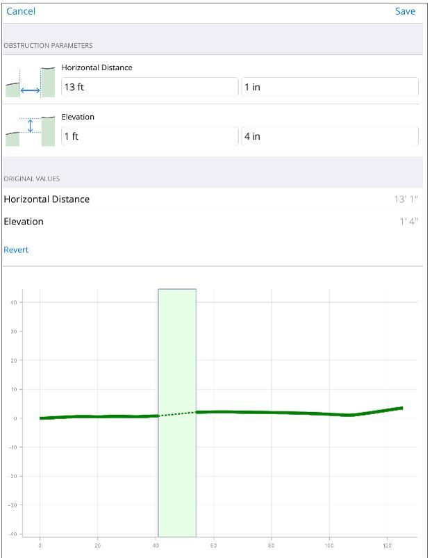
Tap Save.
Things You Should Know
When you need to maintain a specific grade between waypoints, such as drilling for a sewer line, you can use the Maintain grade option to automatically adjust the grade of a selected waypoint to match either the previous or the next waypoint.
On the chart, tap the waypoint you want to adjust. The Nudge Control pane opens and displays the current Distance, Entry Depth, and Entry Angle.
If needed, you can lock the Distance or Entry Depth. Confirm the measurement and then tap the lock icon beside the field.
Tap Maintain grade.
If the Pitch has not been defined, you must enter it. 0.0% is the default value. Enter the desired pitch, and then tap Save.
The blue bar at the top of the pane gives you the distance and direction the waypoint moved.
- To use the new entry point, tap Save.
- To reject the change, tap Revert changes.
In the chart view, tap the Add Marker.
Tap Reference Elevation and fill in the appropriate information.
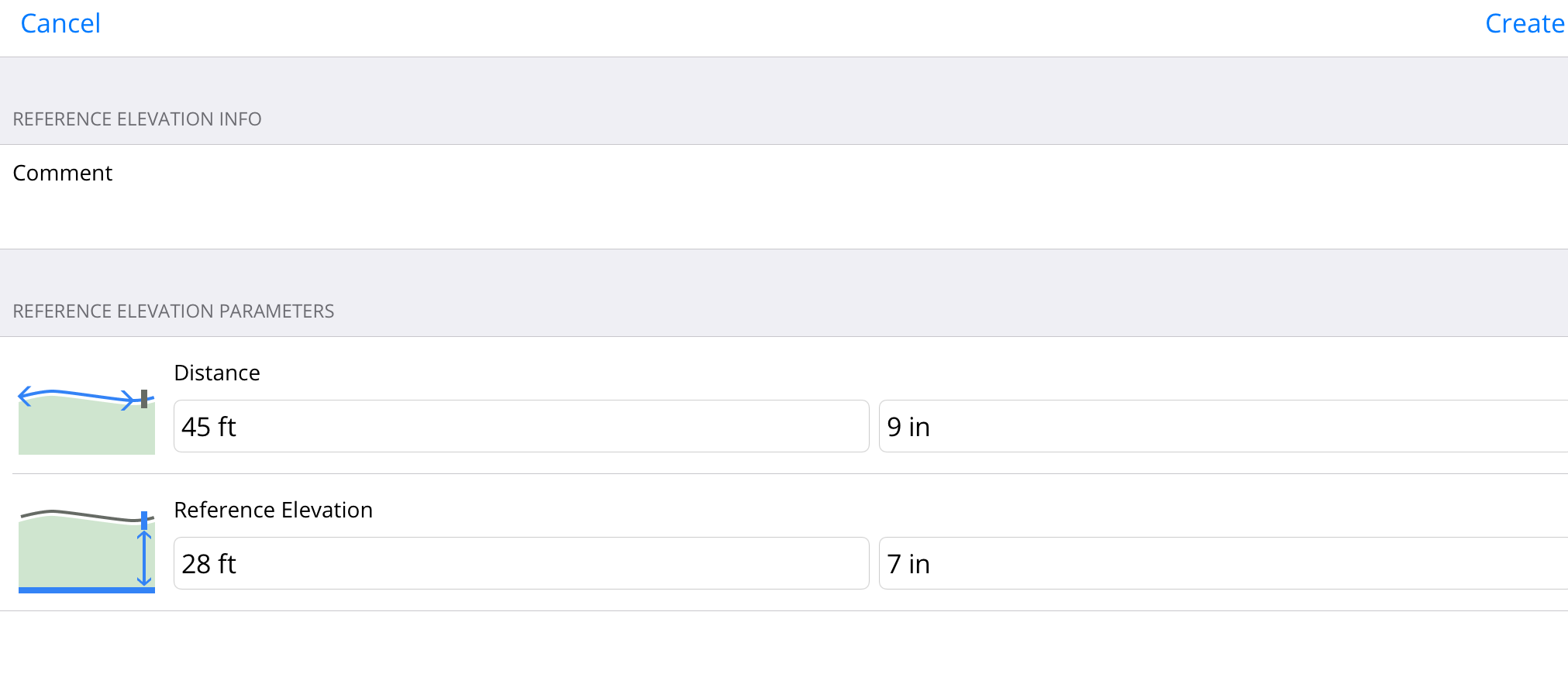
To add the Reference Elevation to the chart, tap Create.
Reference Elevation can be edited like other markers by tapping on the marker on the chart.
On the Jobs list, tap the name of the Job.
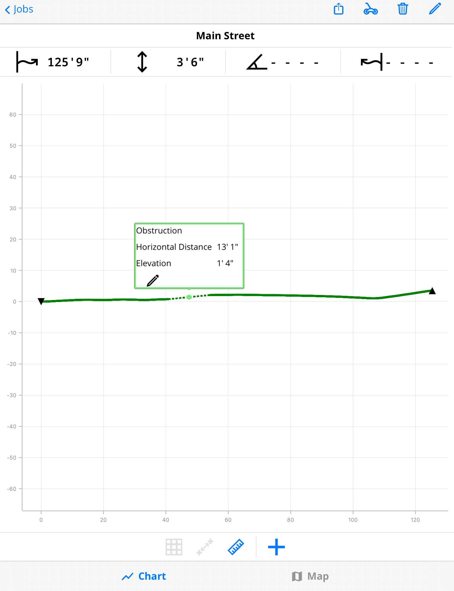
To view details on a specific terrain point, touch and hold on the screen to activate the trackball and drag to the specific point of interest. Continue to hold to view the data.
- Surface distance from the Start
- Elevation difference from Start
- Pitch of the specific point
- Surface distance from the End
- Horizontal distance from the Start
- Horizontal distance from the End
On the Jobs list, tap the name of the Job.
To compare data between two points, tap Measure.
A green box appears between the Start and End Point of your path by default.
To change the area being measured, tap and hold the sides of the box and drag the vertical lines to the points of interest.
- Surface distance of selected area
- Horizontal distance of the selected area
- Elevation difference between the selected terrain points
- Average slope of the terrain of the selected area
The two types of exports are meant to be used for bore planning in other applications.
Accurate terrain data, as well as details on utilities, waypoints, entry and exit points, can all be gathered during bore planning.
The CSV file is a raw data file that includes all the collected data in one-foot increments. This file allows data to be imported directly into other applications that accept CSV imports.
For Vermeer Projects users, go to Settings > Projects > Vermeer Projects to enable the Vermeer-specific CSV export.
The PDF file includes much more detail including the chart, map and details on all the added markers. During the export the user can decide frequency of terrain data points to reduce the amount of data.
Contractor information can be saved and included in PDFs.
Tap Settings.
Under Job Info, tap Contractor Information.
Enter the contractor's contact information.
Tap Save.
Open the job you want to send.
The job needs to be finished before it can be sent.
Tap Upload.
Tap Email.
Scroll through the report. If you need to make any corrections, tap Back and then make any changes.
To share a PDF * or CSV *file, tap Share. Select the app and follow the directions.
The PDF and CSV files are generated automatically, but you cannot view the CSV file on your device.
If you do not want to use the native email editor for your device, select Share and then select another email app. You can enter a default email recipient in Settings, and update the recipients before sending.
If you are sharing a PDF file, the PDF Generation Options dialog pops up. You can change the paper size and select the options not to include the map or terrain data.
You can select which depth information to include:
- Locator Depth * - The best option for DCI locators
- Depth below Terrain * - Usually used with non-DCI locators
For more information on locator depth, see the article, "Depth Display Options" article in the Bootcamp chapter.
Select your options and then tap Continue.
You can also set the PDF defaults under Settings.
"Portable Document File" - PDF stands for "portable document format". PDF files cannot be modified.
"Comma-separated value" is a plain text file that stores data. Each line of the file is a data record with fields separated into columns with commas. The CSV file is used by applications to export and import data.
The depth displayed on the locator to the transmitter.
The vertical depth to the drill head from the terrain. This is often a physical measurement taken with a measuring tape.
Before you start
To transfer an R1 bore plan to an Aurora Display, you will need:
- R1 software version: 2.3 or later
- Aurora display software version: 2.5 or later
- An R1 Bluetooth adapter for the Aurora display (not included)
- An R1 subscription on myDCI for the R1 with the bore plan
If you would like to get a Bluetooth adapter, you can contact your dealer or DCI Customer Support.
For more information about subscriptions, see the article "Add or manage subscriptions" in the Initial Setup chapter.
Open the job you want to send.
The job needs to be finished before it can be sent.
Tap Upload.
Tap Send to Aurora.
The Aurora display must be on and with the Bluetooth adapter inserted. The message, "Ready to Receive" displays in the Aurora display taskbar.
You can track the progress of the transfer on both the R1 App and on the Aurora display.
When the transfer is complete, tap OK.
TECHNICAL SPECIFICATIONS
Product ID/Model Number: TTR1
Accuracy Two-way (elevation): ±2 in over 500 ft (on firm ground when following speed gauge)
Accuracy One-way (elevation): ±2 in over 125 ft (on firm ground when following speed gauge)
Power Source: Built-in lithium-ion battery pack
Battery Life: 40 hrs
Controls: Power button and battery gauge
Voltage, current: 5.0VDC nominal, 500 mA max
Dimensions: 40.9 x 35.3 x 4.4 in
Weight with Battery: 14.0 lb
Smart Device Operating Systems: iOS 11.0 or newer, Android 5.0 or newer
POWER RATINGS
Operational Voltage: 12VDC (nominal)
Operational Current: 5A Max
ENVIRONMENTAL REQUIREMENTS
Operating Elevation: up to 6500 ft
Operating temperatures:
- Run mode: -4°F to 140° F
- Charge mode: 32°F to 104°F
- Storage and transportation: -40°F to 149°F
Relative Humidity: <90%
Dust and Water Ingress: IP65 per IEC 60529
Handling Drop (1 meter): IEC 61010
Vibration: MIL-STD-810G
Electrostatic Discharge: IEC 61000-4-2
COMPLIANCE RATINGS
This equipment complies with the following: Part 15 of the Rules of the FCC; Industry Canada license-exempt RSS standards; ACMA Radio Communications (Short Range Devices) Standard (2014). Operation is subject to the following two conditions: (1) this equipment may not cause harmful interference, and 2) this equipment must accept any interference received, including interference that may cause undesired operation.
This equipment contains Bluetooth Smart Ready Module, Model No. BT121, FCC ID QOQBT121. BT121 operates at 24.02- 2480 MHz frequency. Max output power is 0.013 W.
Patents - https://www.digital-control.com/patents/
Trademarks - https://www.digital-control.com/warranty/
Limited Warranty
All products manufactured and sold by Digital Control Incorporated (DCI) are subject to the terms of a Limited Warranty. A copy of the Limited Warranty is at https://www.digital-control.com/warranty/.
Cleaning the R1
- Press the Power button for 5 seconds to power off the R1.
- Inspect the power level and charge as needed.
- Wipe the R1 clean, especially the wheels.
- Do not pressure wash.
Storage and Transportation
Store in the original system carry case safe from impact, moisture, and excessive temperatures.
Ship in original carrying case or packaging of sufficient durability to prevent mechanical shock to equipment during transport.
Storage and transportation temperatures must remain within -40° to 149° F.
- The batteries contained in this equipment are lithium-ion. Lithium batteries are considered Class 9 Miscellaneous Dangerous Goods under International Air Transportation Association (AITA) regulations. UN 3481 regulations (Lithium ion batteries contained in equipment) apply to this equipment. These batteries must be packaged and shipped by trained and certified personnel only and in accordance with Packing Instructions 970. Never ship damaged batteries.
The batteries contained in this equipment are lithium-ion. Lithium batteries are considered Class 9 Miscellaneous Dangerous Goods under International Air Transportation Association (AITA) regulations. UN 3481 regulations (Lithium ion batteries contained in equipment) apply to this equipment. These batteries must be packaged and shipped by trained and certified personnel only and in accordance with Packing Instructions 970. Never ship damaged batteries.
To prolong the internal Li-Ion battery life:
- Inspect the power level after every use and charge as needed.
- Keep the power level between two and three bars (40%-70%) and recharge frequently without fully charging the battery.
- Store the R1 with the battery charge at approximately two bars (40-50%).
- Store at room temperature.
Do not store the R1 for long periods with an empty battery or in high temperature. This will shorten the battery life.
Always check the battery level before using the R1. The R1 battery drains at the rate of 2% per day while in storage.
Before You Start
The TeraTrak R1 App needs to be installed before you can pair with the R1.
Power on the R1. The Bluetooth icon will flash blue.
In the TeraTrak R1 App, tap R1 Information.
In the list of devices, under Discovered Devices, tap the name of your R1.
If your device doesn't show up on the list, try these solutions. 1) Make sure that the R1 is on and the Bluetooth is enabled on the mobile device. 2) The App has access to Bluetooth.
The paired device will appear under Paired Devices, and the Bluetooth icon turns a steady blue.
Tap Settings.
Tap Distance Units.
Select one of the options:
X' XX" - feet and inches
X.XX' - decimal feet only
X.XX m - meters
Tap Done.
Angle or pitch can be represented as either degrees (°) or percentages (%).
Tap Settings.
Tap Pitch Units.
Select either X.X% (percentage) or X.X °(degrees).
Tap Done.
Stuff You Should Know
Drill parameters are the defaults for drill calculations. Drill parameters typically do not change much from job to job, especially when using the same drill rig.
If you change the drill parameters for specific jobs, it does not change the default settings.
Go back to the Settings screen and tap Distance Units to change between standard and metric.
Tap Settings.
Tap Drill Parameters.
Enter the Rod Parameters:
- Max Bend per Rod
- Rod Length
Max bend per rod can be set to the limits of the drill rod, typically 10% for a 10 ft rod or it can be set to the limits of the product being installed. Enter the Max Bend per Rod in percent.
Enter the Entry Parameters:
- Entry Angle
- Entry Depth *
- First Rod Length
- Straight Drill Distance *
- First rod length
- Straight drill distance
Enter the Exit Parameters.
- Exit angle type: Automatic or Manual
- Exit angle
- Exit depth
Tap Save.
The depth below the surface of the entry point.
The distance drilled straight before any steering takes place and can include as many rods as needed.
Stuff You Should Know
You can select the intervals at which data points will be displayed in reports. For example, every foot or every 5 feet for longer paths.
Tap Settings.
Tap the value for Export Steps Size.
Select one of the interval options (1, 5, 10, 15, 20, 30), which are in feet.
Tap Done.
Before You Start
With Zoom on, you will only see the portion of the path that you are walking. With Zoom off, you can view the whole path.
You can use your fingertips to "pinch" and "spread" when you are not collecting data to shrink and enlarge the chart
Tap Settings.
Tap the Automatically Zoom When Collecting Data to toggle the option on and off.
An invalid drill path is one where the user defined maximum allowable bend per rod has been exceeded. When using the drill calculator functionality (setback and two-point) invalid drill paths are indicated by red dashed lines on the chart view and in the drill table the rods in question are marked as red.
There are a few suggestions to achieve a valid drill path.
- Maximum allowable bend per rod: Ensure it is not set too conservatively (but note that this value is determined by the drill rod or product pipe specifications).
- Desired depth: Try changing the desired depth to reduce the steering required to get to the waypoint.
- Desired pitch: Try changing the desired pitch or use Auto pitch for a more likely valid path.
- Length of the plan: Try extending the plan (up to max of 125 ft) by gathering further data if possible.
When a rod-by-rod plan appears invalid or the App has made assumptions about terrain, an "i" icon may appear in the table. The messages in this section explain the potential issues.
What You Should Know
When the transmitter is pitched down (negative pitch), the locate line on the screen reflects a future position of the transmitter assuming the transmitter stays on the same trajectory (projected depth). The TeraTrak R1 App assumes the terrain to be flat between where the data collection ended and the locate line.
- Locate Line (LL)
- Assumed flat terrain
- Predicted depth reading on locator
- Depth and pitch at desired location
What You Should Know
When the transmitter is pitched down (negative pitch), the locate line on the screen reflects a future position of the transmitter assuming the transmitter stays on the same trajectory (projected depth).
Since the terrain data collection was started at the locate line, the terrain over the transmitter is unknown. The TeraTrak R1 App assumes the terrain to be flat between the locate line and where data collection began.
- Locate Line (LL)
- Assumed flat terrain
- Predicted vertical depth
- Projected depth reading on locator
- Current depth and pitch
What You Should Know
Pitch in percent (%) is defined as vertical distance divided by horizontal distance, often referred to as Rise over Run. The key thing in the calculation is that the horizontal and vertical distances are being used.
- Run
- Rise
For a 10 ft rod being drilled level (0%) the horizontal distance is 10 ft. For that same 10 ft rod drilled at 30% pitch the horizontal distance or run is shorter (9.6 ft) which then affects the pitch calculation.
- Rod at 0%
- Rod at -30%
When drilling at a steeper pitch using percent, the horizontal distance is further shortened as seen in the image. The rise over run calculation will indicate that the maximum bend was exceeded (because of the shorter run) when it was not.
When measuring pitch in degrees this is not an issue as degrees are calculated differently.
- Rod at -30%
- Rod at -40%
Watch a selection of training videos or go to the full library of DigiTrak training videos at www.Youtube.com/DCIKent.
Some videos are only available in English. If needed, please turn on subtitles and automatic translations.
Watch video on YouTube:
TeraTrak R1 - The Wheel, Reinvented - English (1:35 min)
Watch video on YouTube:
TeraTrak R1 Features and Benefits - English (2:00 min)
Watch video on YouTube:
DCI TeraTrak R1 Terrain Mapping and Bore Planning - English (2:03 min)
Watch video on YouTube:
Terrain Mapping with TeraTrak R1 – Three terrain mapping methods - English (1:24 min)
Watch video on YouTube:
DCI TeraTrak R1 Set-back Calculation - English (1:32 min)
Watch video on YouTube:
How to Register Your R1 and Apply a DDM Redemption Code in Your myDigiTrak Account English (1:19 min)
Watch video on YouTube:
How to: Create a Full Bore on the R1 English (2:10 min)
Contact
DCI USA
19625 62nd Ave S, Suite B103
Kent, WA USA 98032
DCI@digital-control.com
1.800.288.3610
1.425.251.0559
DCI Australia
2/9 Frinton Street Southport
Queensland 4215 Australia
DCI.Australia@digital-control.com
+61.7.5531.4283
+61.7.5531.2617
DCI China
368 Xingle Road Huacao Town
Minhang District Shanghai 201107, P.R.C
DCI.China@digital-control.com
+86.400.100.8708
+86.21.6432.5186
DCI Europe
Brueckenstraße 2
97828 Marktheidenfeld Germany
DCI.Europe@digital-control.com
+49.9391.810.6100
+49.9391.810.6109
DCI India
Unit No. 1022, 10th Floor DLF Tower B Jasola District Center
New Delhi 110025 India
DCI.India@digital-control.com
+91.11.4507.0444
+91.11.4507.0440
DCI Philippines
404-405 Energy Opt. Bldg Prime St, Madrigal Business Park 2
Alabang Muntinlupa City, Philippines 1780
DCI.Philippines@digital-control.com
(02)79802647
+632-79802647