
| Device (Model Number, Product ID) | Relative Humidity | Operating Temp. |
|---|---|---|
| DigiTrak®Ares® (AEO2, DR-ARES) | <80% | Operation |
| DigiTrak Lithium-Ion rechargeable: battery pack- G4 (MBP6v1) | <80% | -4 – 140° F (-20°C – 60°C) |
| DigiTrak Aurora® remote display (AF8/AF10) | <90% | -4 – 140° F (-20°C – 60°C) |
| DigiTrak SuperCoreTM transmitter (RTP, DTS15/DT15p) | <100% | -4 – 220° F (-20°C – 104°C) |
| DigiTrak Classic-Core transmitter (RTP, DT15/DT15p) | <100% | -4 – 220° F (-20°C – 104°C) |
| DigiTrak SuperCell-R rechargeable battery pack (SR40-R) For safety, battery pack turns off at 185°F (85°C) | <90% | Operation |
| DigiTrak Li battery charger (RBP2, SR40-R) (Cradle is model RBC1; with Mascot brand LiCh2.5 charger brick, model 3546 LI ) | <90% | 45°F – 104°F (5°C – 40°C) |
DigiTrak Ares User Manual
DCI DigiGuide 2026.03.13

DCI DigiGuide User Manual
2026.03.13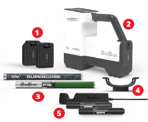
- Ares rechargeable locator batteries (USB-C)
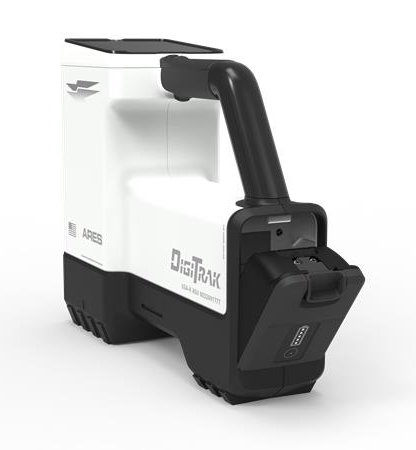
- DigiTrak Ares locator
- SuperCore DTS15p and Classic-Core DT15p transmitters
- Detachable Ares locator saddle mount
- LiR transmitter battery charger and cable (SuperCore only)
These are the basic steps to prepare your Ares Guidance System for locating.
- Register your locator on mydci.digital-control.com to claim your warranty. For instructions go to Add equipment or use the QR code in the Welcome packet.
- Power on the locator, the remote display, and the transmitter. Make sure your locator and transmitter is for the same region. For instructions, go to Jobsite setup chapter.
- Select the frequency bands for the transmitter using defaults. For instructions, go to Use transmitter defaults. You can also use the Eagle Tech-powered Automatic selection.
- Calibrate and validate the locator and transmitter's above-ground-range (AGR). For instructions, go to the article Calibrate.
- Optionally, you can:
- Set roll offset for when the 12 o'clock position of the transmitter on the locator display does not match that of the drill head's position. For instructions, go to the article Enable and set roll offset.
- Set height-above-ground (HAG) for the height you intend to hold the locator above the ground while taking depth readings. For instructions, go to the article Set Height-Above-Ground (HAG).
- Set up Bore logs to document the job. For instructions, go to the Log While Drilling (LWD) manual.
- Start locating. For instructions, go to the article Basic Locating.
Falcon Users - Look for information boxes that call out the differences between Falcon and Ares.
Interference, also called noise, varies by intensity and frequency depending on where you are and even the time of day. That’s why it’s important to find the best frequencies for every bore. This is called frequency optimization, and only DCI's DigiTrak locators have it. Using frequencies with the highest probability of success against noise increases locating accuracy and reduces the risk of tripping out.
When using the Ares locator's Automatic selection feature to select frequencies, DigiTrak Ares Eagle Tech analyzes noise along the entire bore path and picks from over 8000 frequencies to give the best depths and data ranges in the worst conditions across the entire bore. While DigiTrak Ares looks for the best frequencies, you can keep your eyes on your surroundings.
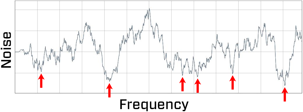
Noise - Noise
Frequency - Frequency
Select two bands and switch between them mid-bore if needed. You can include both wideband and rebar on the same job on one Ares SuperCore transmitter or Classic-Core transmitter.
There are three ways to select your best frequencies:
- Transmitter defaults - Two clicks load the two preset bands selected for your region, and fine tunes the frequencies in these bands for your current job.
- Automatic selection - Walk and scan the entire bore path and let DigiTrak Ares recommend the best two bands from over 8000+ frequencies.
- Manual selection - Hand-select your bands. Walk and scan key points of your bore path, queue the potentially best bands, and then select two bands. This is a good option if you only want to scan the deepest part of the bore or where you expect the worst interference.
Falcon User
The DigiTrak Ares locator Eagle Tech scans the entire bore path, not a single location like Falcon.
If you prefer to hand-select bands like you did for Falcon, or you only want to scan the deepest part of the bore or a tricky location with the worst noise, use the Manual selection, Manual selection is very similar to Falcon's frequency optimizer technology. It still uses enhanced frequency optimization to scan and display the best bands but with Ares you can queue a band, scan again before selecting the second band.
The frequency graph now displays depth bars with a deepest bore line, instead of noise bars making it easier to visualize what bands will be successful for different parts of a job.
Falcon Users - Look for information boxes that call out the difference between Falcon and Ares.
DCI DigiGuide App
The DCI DigiGuide App is your online manual.
- Step-by-step instructions.
- Tips and tricks to help solve problems.
- Troubleshooting help, including links to videos.
- Bookmark articles, share articles with other DigiGuide users, or download pdfs of full articles and manuals.
- A living document. The DigiGuide is updated multiple times a year with new features, information, and links to videos.
Download the app from the App Store.
TeraTrak App
The TeraTrak App is your TeraTrak's digital companion.
Create rod-by-rod bore plans to cut down on steering time—and maximize your drilling time.
- Visualize your path – Mark waypoints and utilities to plan your bore up to 75 ft (23 m).
- Find your setback – Easily calculate where to place your rig for a valid entry point.
- Stay on course – If you find yourself off your bore plan, your app can help you get back on track.
Download the app from the App Store and then learn more about the TeraTrak R1 in the TeraTrak R1 manual in the DCI DigiGuide App.
myDCI portal
The myDCI web portal is your one-stop, centralized hub to manage your DCI equipment with real-time information. On the portal authorized users can:
- Create a free company account and invite additional users
- Register equipment and view your warranties
- Purchase and manage subscriptions, such as LWD Cloud and Trak-It
With the DigiTrak LWD(Log-While-Drilling) app, you can view and manage real-time pilot bore data from your locator.
DigiTrak LWD App
- All-in-one solution – View all your bore logs in one location
- Enhanced precision – Get detailed position data about each rod
- Increased transparency – Mark obstacles or utilities with ease
- Requires a free company and individual user account on the myDCI portal to transfer data from the locator
- Requires an LWD Cloud subscription on the myDCI portal to store files in the LWD Cloud or share files
Download the app from the App Store and then learn more about data logging in the LWD manual in the DCI DigiGuide App.
- Only operate your DCI guidance system in accordance with the operating instructions for your system.
- Serious injury and death, as well as property damage, can result if underground drilling equipment strikes a natural gas line, high-voltage electrical cable, or other utility.
- Work slowdowns and cost overruns can occur if you do not use your system correctly.
- Properly calibrate your DCI guidance system anytime you change frequencies, transmitters, or drill heads and validate the calibration before every drilling project. If you fail to do so, depth readings will likely be inaccurate.
- Interference can lead to inaccurate depth readings and/or interruption of data. See "Special Notes About Interference" for more details.
- DCI guidance systems are used to locate and guide the transmitter (housing) underground. They cannot be used to locate underground utilities.
- Failure to find the front and rear locate points can lead to inaccuracies which may result in drilling off-path and striking an underground utility.
- The locate line on a DCI locator does not indicate the position of the drill head. DCI locators track the transmitter in its housing, which sits behind the drill bit. Also, when drilling steep and/or deep, the locate line may indicate a position behind or ahead of the transmitter. Please see "Steep and Deep" under Advanced Topics for important information about accurately locating the drill head when drilling steep and/or deep.
- Ensure that all underground utilities have been located, exposed, and/or accurately marked prior to drilling. Follow all proper safety precautions, such as potholing.
- DCI equipment is not explosion-proof and should never be used near flammable or explosive substances.
- Wear jobsite protective/safety clothing such as dielectric boots, gloves, hard hat, high-visibility vest, and safety glasses.
- Install transmitters into the drill housing as soon as possible after powering on. If you can't, unscrew the cap to power off the transmitter until you can install the transmitter into the drill housing to reduce RF exposure.
- Comply with federal, state, and local governmental regulations (such as OSHA) and all other customary or required safety precautions.
If you have any questions about the operation of your guidance system, please contact DCI Customer Service for assistance.
System working altitude: up to 6562 feet (2000m).
Operation may be compromised if the equipment is subjected to conditions outside these specified limits.
Ship in original carrying case or packaging of sufficient durability to prevent mechanical shock to equipment during transportation. See the Storage and Shipment of Batteries for the more information about that equipment.
If you have any questions about the operation of your guidance system, please contact DCI Customer Service for assistance
Charger is intended for indoor use and is not waterproof or dustproof. To avoid overheating, make sure there is sufficient air circulation around the charger when in use; do not cover the charger.
Charger must be kept away from heat sources and may not be used in environments with flammable or explosive atmospheres.
Charger is only intended for use with DCI SuperCell-R Li 2.5A batteries. Do not use the charger with other types of batteries.
Use only the power cords provided with your charger by DCI.
Unplug charger when not in use.
Charger contains hazardous voltages and there are no user-replaceable parts inside. Never attempt to remove the cover. Contact DCI Customer Service for assistance.
Do not dispose of the charger with municipal waste. See the article "Equipment and Battery Disposal."
Remove the batteries from all system components during shipping and prolonged storage. Failure to do so may result in battery leakage, which may lead to risk of explosion, health risks, and/or damage.
Store and transport batteries using a suitable protective case that will keep batteries safely isolated from one another. Failure to do so may result in short circuits, which may lead to hazardous conditions including fire.
Lithium-ion batteries must be packaged and shipped by trained and certified personnel only. Never ship damaged batteries.
If you have any questions about the operation of your guidance system, please contact DCI Customer Service for assistance. Connect to DCI Customer Service with the Contact link in the DigiGuide App or find a list of offices in the back of any printed DigiGuide manual and on the DCI website: digital-control.com.
If you plan to store the battery packs for any period of time, please follow these guidelines:
Store and transport batteries using a suitable protective case that will keep batteries safely isolated from one another. Failure to do so may result in short circuits which may lead to hazardous conditions including fire.
Do not store the battery pack at temperatures greater than 113° F (45°C).
Do not store the battery pack in a fully discharged state.
Do not store the battery pack in the battery charger.
Do not store multiple batteries together where their terminals or other loose conductive materials may contact one another and cause a short circuit.
Never ship damaged batteries.
If a lithium-ion battery pack will be stored for an extended period of time, pre-charge the battery to a charge level of 30% to 50% (two or three LEDs illuminated on the meter).
Do not store the battery pack for more than one year unless it is periodically recharged to the 30% to 50% level.
Lithium batteries are regulated by UN3480 and UN3481 lithium-ion batteries.
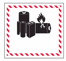
Lithium batteries are considered Class 9 Miscellaneous Dangerous Goods under International Air Transportation Association (IATA) regulations; IATA regulation and Ground Transportation regulations 49 CFR 172 and 174 apply. These batteries must be packaged and shipped by trained and certified personnel only. Never ship damaged batteries.
This symbol on equipment indicates that the equipment must not be disposed of with your other household waste.
Instead, it is your responsibility to dispose of such equipment at a designated collection point for the recycling of batteries or electrical and electronic equipment. If the equipment contains a banned substance, the label will show the pollutant (Cd = Cadmium; Hg = Mercury; Pb = Lead) near this symbol.
Before recycling, ensure batteries are discharged or the terminals are covered with adhesive tape to prevent shorting.
The separate collection and recycling of your waste equipment at the time of disposal will help conserve natural resources and ensure it is recycled in a manner that protects human health and the environment.
For more information about where you can drop off your waste equipment for recycling, please contact your local city office, your household waste disposal service, or the shop where you purchased the equipment.
U.S.: Contact The Battery Network’s Drop-off Locator at 1-877-2-RECYCLE or visit www.batterynetwork.org.
Ce symbole figurant sur l'équipement indique qu'il ne faut pas le jeter avec les ordures ménagères.
Il vous incombe en effet d'éliminer ce type d'équipement en l'amenant à un site de récupération désigné pour le recyclage des batteries/piles ou d'appareils électriques et électroniques. Si le matériel contient une substance interdite, l'étiquette indiquera le polluant (Cd = cadmium ; Hg = mercure ; Pb = plomb) à côté de ce symbole. Avant de recycler les batteries, assurez-vous qu'elles sont déchargées ou que les bornes sont recouvertes d'un ruban adhésif pour éviter les courts-circuits. La collecte séparée et le recyclage de votre matériel usagé au moment de l'élimination permettront de conserver les ressources naturelles et de veiller à un recyclage en bonne et due forme, qui protège la santé humaine et l'environnement. Pour plus d'informations sur les sites où vous pouvez déposer votre matériel usagé à recycler, veuillez contacter les autorités municipales, votre service d'élimination des déchets ménagers ou le lieu d'achat du matériel.
Locating in the horizontal directional drilling (HDD) industry was initially based on locating a buried cable by sweeping the locator back and forth to find the highest signal strength (peak signal), indicating that the locator was over the cable. Unfortunately, this method did not always guarantee an accurate location of the cable, nor did it provide any depth information.
This “peak signal” method was adapted to HDD with the introduction of a transmitter that provides information on the position and depth of the drill head. However, this method is unreliable and inaccurate because the peak signal strength is not always directly above the transmitter housing.
In addition, peak signal locating doesn’t show where the drill tool is headed. Think of drilling like driving a car: it is more effective to look ahead through the windshield to see where you are going than to look down at the road through the floorboard to keep the car (drill tool) on the road (drill path).
The DigiTrak Ares locator is a new generation of locator with new technology, upgraded features, and more power. All presented on bigger screens with informational text and better workflows.
- Simplified workflows and no more hidden menus or shortcuts.
- AI-powered Eagle Tech scans your entire bore path and selects the best frequencies out of 8 times as many frequencies than Falcon. You can also use the best pre-selected frequency bands for your region.
- No up or down bands. Choose A or B. How you load the transmitter battery doesn't matter.
- Ares SuperCore transmitters have more power, range, and a proprietary rechargeable battery. The Classic-Core transmitter can use multiple types of batteries. Both transmitters have two bands, which can include rebar, so you can switch mid-bore.
- Target mode and predicted depth mode provides predicted depth below the locator position.
- Rechargeable locator and SuperCoretransmitter batteries. The locator battery uses a standard USB-C connection.
- Over-the-air updates over Wi-Fi keep your locator up-to-date.
- Bluetooth allows pairing and easier calibrating transmitters in the housing above ground and calibrates all power levels and both bands at the same time.
- Built-in GPS with location tracking and lockout mode (with a Trak-It subscription)
- Transmitter SnooZe can be turned on and off from the locator.
- A universal saddle replaces the TrakStand and is compatible with a wider range of off-the-shelf tripods.
- More languages with more coming with future releases.
Falcon Users - Look for tips that highlight differences from the Falcon locators.
While DCI guidance systems provide you with technology to combat active interference (and passive interference, with the Sub-K® rebar enabled transmitter), no guidance system is immune to all interference.
Interference can lead to inaccurate depth readings and/or interruption or loss of data. Never rely on data that does not display quickly and/or remain stable.
The DigiTrak Ares uses Eagle Tech to select frequencies based on measured interference at a specific time and location.
Interference levels change with time and with even minor changes in location. The frequency optimizer is not a substitute for prudent operator judgment. If performance drops while drilling, consider switching to the other selected band or use Max mode *.
An Attenuation signal icon on the screen can indicate signal attenuation * due to the presence of excessive interference, which can make depth readings inaccurate.
Attenuation is normal in shallow depths less than 8 ft (2.4 m). If the signal strength is in a red box this indicates extreme interference. Depth and locate points may be compromised and the locator will not calibrate.
Interference is classified as either active (generating electro-magnetic signals) or passive (material that can conduct or block electro-magnetic signals). Sources of interference may include:
| Active | Passive |
|---|---|
|
|
If you have any questions about the operation of your guidance system, please contact DCI Customer Service for assistance.
Max Mode can stabilize roll/pitch data and depth readings when drilling at the transmitter’s range limit due to extreme depth or interference, which will vary by jobsite. See the Max Mode topic for use and important safety information.
Il localizzatore attenua automaticamente il segnale del trasmettitore quando si effettua la localizzazione a profondità ridotte per ridurre l'eccessiva intensità del segnale. L'attenuazione è attiva ogni volta che appare una A sullo schermo della Modalità Localizzazione. L'attenuazione può anche indicare la presenza di interferenze eccessive, che possono rendere inaccurate le letture della profondità.
L'attenuazione è normale quando il localizzatore è vicino al trasmettitore; l'attenuazione durante la calibrazione è un avviso a spostarsi e calibrare in un'area con meno interferenze. Il localizzatore non si calibrerà quando la forza del segnale lampeggia, il che indica la presenza di interferenze estreme.
DCI’s design uses a “locate point” in the transmitter signal. The Front Locate Point (FLP), which is out ahead of the transmitter, shows where the transmitter housing is heading.
DCI invented the Ball-in-the-Box user interface to make it quick and intuitive to find a locate point, speeding up drilling jobs: just move the locator so the ball moves into the box on the screen.

Finding a locate point also helps you find the drill head itself.
There is a second locate point behind the transmitter called the Rear Locate Point (RLP). The two locate points, combined with a Locate Line (LL), pinpoint the precise location of the transmitter housing below ground.
They are arranged like an airplane, where the Front Locate Point is the plane’s nose, the Rear Locate Point is the tail, and the Locate Line is the wings.

If your drill path requires a consistent depth or to maintain a constant pitch, use the predicted depth feature at the Front Locate Point. This eliminates the need for depth readings over the transmitter, speeding up the drilling process.
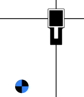
When a transmitter is level (zero pitch) underground:
- the locate points (FLP and RLP) are at equal distances from the transmitter
- depth displayed on the locator is the actual depth, and
- the Locate Line (LL) indicates a position above the transmitter.
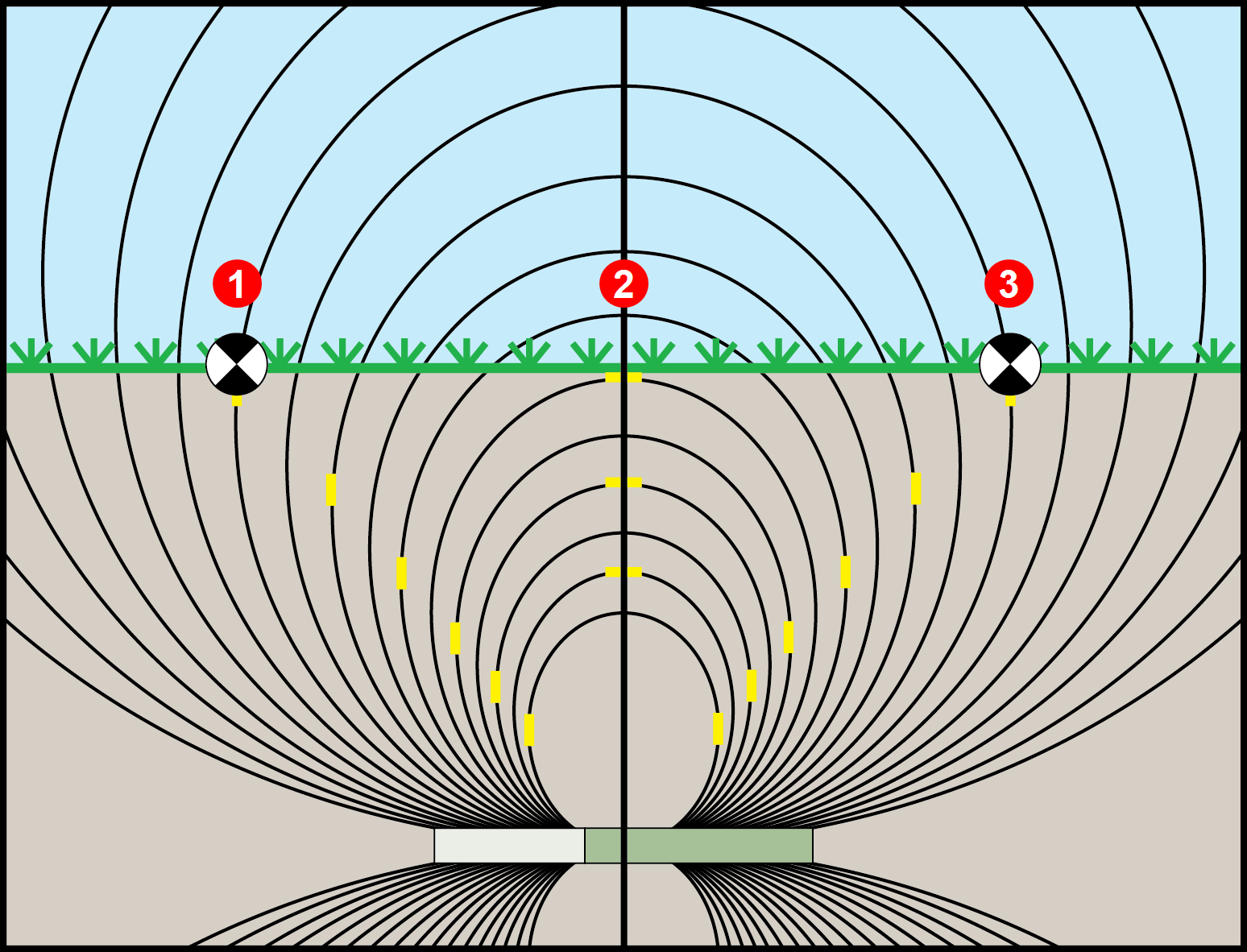
- RLP
- LL
- FLP
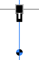
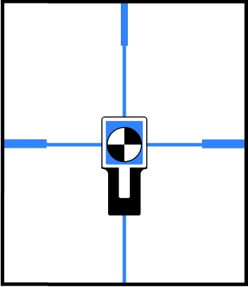
When the transmitter is pitched up or down, the transmitter signal field also tilts.
When the transmitter is pitched down (negative pitch), the locate line on the screen reflects a future position of the transmitter, assuming the transmitter stays on the same trajectory (projected depth).
When the transmitter is pitched up (positive pitch, shown below), the locate line on the screen reflects a position behind the transmitter.
The depth reading on the locator is based on the projected depth point, which is not the same as the actual depth of the transmitter.
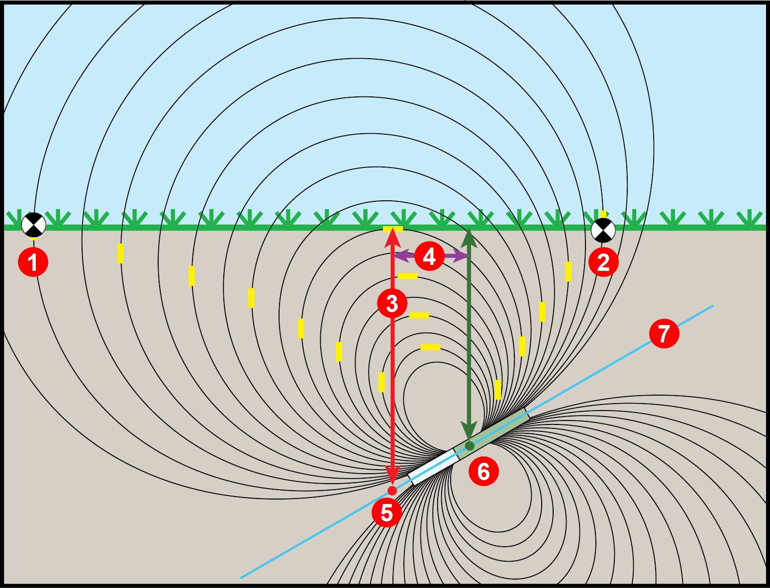
- RLP
- FLP
- LL
- Fore/aft offset
- Projected depth
- Transmitter at positive pitch
- 30% (17°)
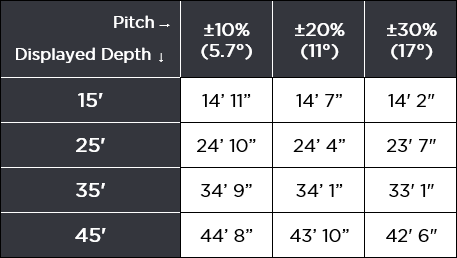
The differences in position and depth between the projected depth point and the actual location of the transmitter can be relatively small at low pitch and/or shallow depth.
When drilling at a steep pitch and/or significant depth, the differences are greater.
For example, if the transmitter is at a plus or minus 30% pitch and a 33'1" (10.1 m) depth, the locator depth reading will be 35' (10.7 m) (just under 6% difference from actual depth) and the locate line will be 6'6" (2 m) from being directly above the transmitter (-30% places the LL ahead and +30% places the LL behind).
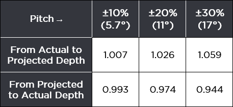
You can use the pitch and the projected depth reading on your locator to determine the actual depth and the position (fore/aft) of the locate line:
Actual Depth
Fore/Aft Offset
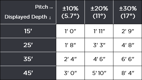
For a given pitch, you can calculate actual or projected depth:
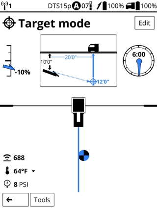
The Target mode guidance method allows the locator to be placed ahead of the drill head and used as a steering target.
Use it to distance the locator from rebar that is causing signal interference and to drill where walkover locating is not possible.
Target mode is typically used on a straight drill path, not on a curved bath, terrain changes, or to correct a significantly off-course bore.
You can set a target depth and then use Target mode with left/right and up/down steering accurately up to 35 ft (10.7 m). After this range, you can still use left/right steering (remote steering) for the entire range of the transmitter.
Utility companies and municipalities increasingly require a digital as-built report to ensure drilling parameters were met.
The Bore log feature on your Ares locator lets you easily capture and store the rod-by-rod data of your pilot bore, including adding the depth and type of utilities, pins and flags to mark features, and include offset and deviations for the running line.
When used with DCI’s DigiTrak LWD app, geo-tagging the entry and exit automatically ties the as-built to a physical location.
With a TeraTrak R1 App, create bore plans and import them directly into your Aurora display to compare rod placement to the planned bore.
With a free company and user account on the myDCI portal, upload bore logs from your locator to the LWD App on your mobile device. With an additional LWD cloud subscription, you can upload and store your files on myDCI and share the files with the rest of your company even during drilling to show progress to back-office personnel.
After importing your bore log file into the Log-While-Drilling (LWD) software, you can edit, annotate, and finalize the precise report you or your customer requires.
On the DigiTrak Aurora remote display, use our free LWD Live app to view the drill profile in real-time as each rod is completed.
The Ares locator has a four-way D-pad on top and a trigger switch under the handle to navigate menus and select options.
To turn on the locator, squeeze and hold the trigger for 2-3 seconds.
Use the D-pad to scroll up or down menu options and buttons and then squeeze the trigger to select the button or option. The active button is blue.
The back arrow button usually takes you back to the previous screen or to the screen indicated by the icon. In this example, the back arrow button takes back to the Locate mode screen.

On most menus, scrolling to the left takes you to the top of the menu. If you are at the top of a list, scroll up to skip to the bottom of the list and scroll down at the end of a list will take you back to the top.
Falcon Users - The toggle has been replaced with a flat four-way D-pad switch. Shortcuts have been replaced with menus and buttons.
The Home screen is an at-a-glance view of your guidance system, including paired transmitter, active bands and frequencies, battery life, connectivity, and quick access to menus.
The Locate mode, Depth, Estimated Depth, and Target mode screens are the primary screens you will use for locating.
When the locator is detecting a signal from a transmitter, the Locate mode and Target mode steering screens provide real-time data about the transmitter’s location, temperature, pitch, roll, signal strength, and downhole annular fluid pressure *.
From the Locate mode and Target mode steering screens, you can take a depth reading at the Locate Line * (LL) and predicted depth at the Front Locate Point *(FLP). At any other time, you can take a depth estimate between the LL and FLP.
The pressure of the drilling fluid in the space between the drill string and the bore wall (the annulus).
An imaginary line directly under the locator.
An imaginary line ahead of the locator that indicates where the transmitter is heading. The FLP is where you take a predicted depth reading.
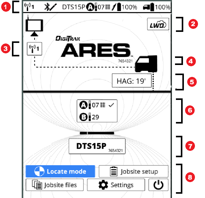
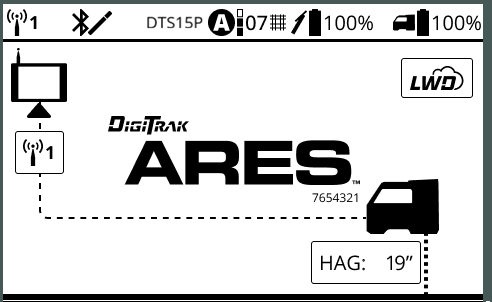
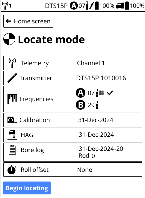
Home screen
- Status bar - telemetry, Bluetooth, transmitter (Tx) settings, transmitter battery and locator battery life
- myDCI portal subscriptions
- Remote display telemetry channel*
- Locator type and serial number*
- HAG (Height-Above-Ground) set distance*
- Transmitter settings (bands, power level, frequencies, rebar enabled, and active frequency)*
- Transmitter model and serial number*
- Navigate to other screens and off button
*Click on these items to see more detail or make changes.
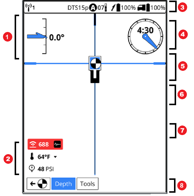
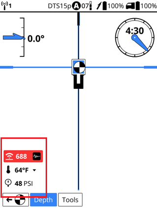
Locate mode screen
- Pitch
- Transmitter data (attenuation warning, signal strength, temperature, and pressure)
- Telemetry, transmitter type, band, power mode, transmitter battery life, and locator battery life
- Drill housing clock (offset off)
- Box target (changes color to blue, if the ball is in the box and centered on both crosshair lines)
- Crosshair lines (blue, if the ball is centered on the line)
- Ball (blue and white if on a crosshair line or in the target box)
- Depth reading button (highlighted) and Tools button
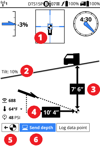
Locate depth screen
- Ball-in-the-Box is at a locate point (FLP, LL, or RLP)
- Ground tilt
- Transmitter depth at FLP
- Horizontal distance between transmitter and locator
- Return to Locate mode screen
- Send depth data to remote (selected)
If the transmitter is pitched, the FLP, LL, and RLP will have different depth readings.
If you take a depth reading and are NOT on a locate point or the Locate Line (LL), you will get a depth estimate reading but will not be able to send the data to the remote.
Falcon Users - Unlike the Falcon, when you take a depth reading it is not automatically sent to the remote display.
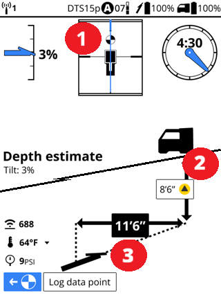
Depth estimate screen
- Ball-in-the-Box is beyond the LL and a locate point is not in the box.
- Transmitter depth estimate
- Horizontal distance between transmitter and locator
Estimated depth should only be taken on the line between the LL and the FLP and is inaccurate beyond 35' (10.7m) from the locator or if behind the LL or off to side of the centerline. The locator must be facing down the bore path with the transmitter pointing at the Ares battery pack.
You can log a rod from an estimated depth reading, but only the pitch or a blank rod is logged.
The further the drill head is from the locator the less accurate the estimated depth calculation. Not accurate past 35' (10.7m). For safety, do not use estimates alone to determine a position for crossing utilities or obstacles. The depth calculation should therefore only be used as an estimate of the projected path.
Registering your DCI equipment at myDCI.digital-control.com allows you to:
- Activate product warranties
- Obtain and assign subscriptions to equipment, such as Trak-It for Ares locators, the R1 App for bore planning, or the LWD App for transferring bore logs to a device
- Enable theft tracking options for DigiTrak Ares locators
For more information about the myDCI portal and registering your equipment and purchasing subscriptions, go to the myDCI manual in the DigiGuide App.
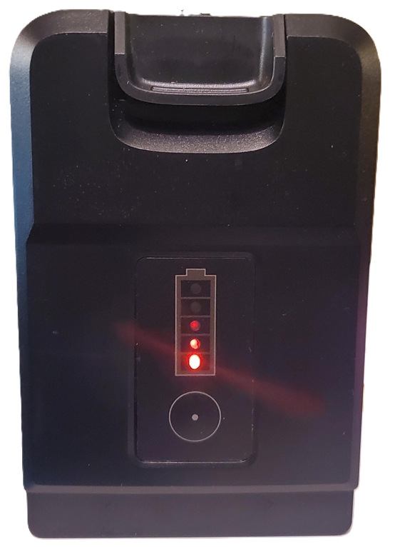
Check the charge level of your locator battery; each of the five lights on a Li-ion battery represents about 20% capacity.
A 100-watt USB-C cable is recommended for charging. If the battery is completely discharged, it may take a several minutes until the first indicator light appears. You can also view locator battery charge level in the top status bar of most screens.
Insert battery in the locator.
Pull the trigger and hold for 1-3 seconds to power on.
Click to confirm you’ve read the manual.
The regional code for the locator and the transmitter must match. If they don't, contact your DigiTrak dealer.
On the transmitter, look for the globe icon on the etching. The letter or number must match the region code for the locator.
To find the region code for the locator, on the Home screen, select Settings, scroll down to the bottom of the list and select About this locator, and then select System information.
The Region code is the letter after the dash.
Before You Start

You can download software updates with new features and upgrades for your DigiTrak Ares locator over Wi-Fi, including stable mobile hotspots. The locator automatically disconnects from Wi-Fi after the update is complete.
For more information about connecting to Wi-Fi on your locator, see the article Connect to Wi-Fi.
Some software updates are optional. However, some features and functionality will not be available without the current software. If a software update is available, a message is displayed on the equipment page on the myDCI portal. You can also check for updates in Settings.
From the Home screen, scroll down and select Settings.
On the Settings page, under System, select Software updates.
Select the network to use and then enter the password using the D-pad and trigger. The locator will remember the password the next time you connect.
If a Wi-Fi network is hidden and doesn't broadcast their SSID, you can still connect to these networks if you know: 1) the network name or SSID 2) the type of encryption used by the network 3) the network password.
After connecting, the locator checks for updates.
- If the locator software is up-to-date, the current version is displayed, with a message. Select Close to return to the Settings menu.
- If the locator software needs an update, click Download and Install, and then select Begin update. When the update is complete, the locator will restart.
- If the update fails, contact DCI Customer Support.
Do not turn off the locator or switch screens until the update is complete. Time to update will vary depending on connection speed and may take several minutes. Make sure the locator battery is at least half full, so that the update is not interrupted.
Before You Start
You can personalize the DigiTrak Ares locator.
- Change how the screens are displayed (dark or light and brightness)
- Select how dates and time are displayed
- Turn sounds on or off
- Change the locator language (View the list *)
- Select how depth and distances are displayed (feet or metric)
- Select how pitch, temperature, and pressure units are displayed
From the Home screen, go to Settings.
On the Settings screen, scroll down to the options you want to change.
The changes are immediate.
English (US)
বাংলা (Bengali)
汉语 (Chinese)
Dansk (Danish)
Nederlands (Dutch)
Français (French)
Deutsch (German)
हिन्दी, हिंदी (Hindi)
Italian (Italiano)
Polski (Polish)
Português brasileiro (Portugal-Brazil)
Español (Spanish)
Русский (Russian)
Before You Start
Use Height-Above-Ground (HAG) to set a height measurement on the locator so you don’t have to put it on the ground for a depth reading.
Raising the locator above the ground also provides separation from underground interference that might otherwise reduce the transmitter’s range or cause variable readings. It also improves telemetry back to the remote display.
If HAG is turned on, you can see the height set on any of these screens.
- Home screen
- Locate screen
- Locate tools screen
- Depth screens
Turning HAG on or off here for Locate mode, does not turn it on or off for Target mode. They are treated as separate settings. For details on HAG in Target mode, go to the article,"Locate with Target mode."
Falcon Users - The Ares locator remembers the HAG setting and doesn't automatically turn it off when the locator is turned off.
Measure the distance between the ground and the bottom of the locator using a tape measure.
- To measure for hand-held HAG, hold the locator at your side as if you were holding a suitcase.
- To measure on a stand, extend the legs to the desired length and lock them securely, and seat the locator firmly into the saddle, and the saddle onto the stand.
From the Home screen, select Jobsite setup.
On the HAG screen, use the up and down arrows to enter the height, and then select Save.
Ares locators pair with transmitters via Bluetooth and can be paired with multiple transmitters, but only one transmitter can be active at a time.
If there are no transmitters currently paired with this locator, the Home screen will prompt you to add one.
If a transmitter has been paired before or you want to add a new transmitter, you can find the list of transmitters in a couple of places:
- On the Home screen, select the transmitter model and serial number box.
- On the Jobsite setup screen, select Transmitter.
If there are no transmitters paired with this locator, on the Home screen, under the "No transmitter selected" warning, select Add transmitter.
If you want to change the transmitter currently paired, select the transmitter button, and then on the Transmitter list screen or select Add transmitter.
If you select a previously paired transmitter you can skip the pairing step and go directly to adding frequencies.
Power on your transmitter by inserting the batteries and screwing on the cap. Power on the locator by holding the trigger for 2-3 seconds.
The Bluetooth range for the locator and transmitter is about 10-13 feet (2-4 meters). The transmitter can connect and pair within that range even if it is in a drill housing. The transmitter's Bluetooth LED flashes green when ready to pair and blue when paired.
After you see the confirmation message, click Frequencies to select bands and frequencies.
Install transmitters into the drill housing as soon as possible after powering on. If you can't, unscrew the cap to power off the transmitter until you can install the transmitter into the drill housing. The transmitter will connect to the locator via Bluetooth while in the housing. Make sure the housing slots are clear of mud and debris, so that the locator can detect the Bluetooth signal from the transmitter.
Before You Start
Your locator comes preloaded with the two frequency bands that work best in your region. When you open the Transmitter defaults screen, the locator will scan the environment to refine the frequencies.
The defaults automatically set the lower frequency at standard power level to band A. Before loading, you can also edit A or B to add rebar frequencies.
From the Home screen, select Jobsite setup, and then Frequencies.
On the Frequencies menu, select Transmitter defaults.
The Transmitter defaults screen displays a simplified version of the Frequency screen. If this is the first time this transmitter has been set up, the Current area will be empty.
Select Bore depth and enter the expected maximum bore depth for this job. The bore depth line will adjust to the new depth.
Start where the bore is the deepest or where the highest interference is expected. Before starting the environmental scan, if the paired transmitter is on (check the status bar) and within Bluetooth range, the locator will turn off the transmitter signal.
The environmental scan fine tunes the frequencies. Confirm the depth bars reach the bore depth line of the job.
Return to Bluetooth range of the transmitter and then select Load. The locator will turn the transmitter signal back on (check the status bar) and load the frequencies.
The transmitter is connecting to the locator.
If loading the frequency fails, try a wake-up roll on the transmitter and try again. If the situation persists, see the Troubleshooting chapter.
After the bands are loaded onto the transmitter, select Calibration to continue the transmitter setup.
If the bore depth is marginal, review the power levels for the suggested bands. If there is a higher power level available, you could continue, load and save the suggested frequencies, and then after calibration, change the power level.
If the Transmitter defaults are not suitable for this jobsite, try using Automatic selection to find the recommended bands.
You can also use Manual Selection to hand select the bands for the job. For more information, see the related articles in the Jobsite Setup chapter of the DCI DigiGuide App.
If you want to change the default frequencies and power levels or add rebar for the next time you use Transmitter defaults, select "Edit defaults."
Before You Start
After adding and pairing a transmitter, Eagle Tech exclusive to the DigiTrak Ares locator, will walk you through choosing the best frequencies for the jobsite using DCI's AI-assisted Automatic selection with smart prompts and on-screen step-by-step instructions. If there are problems, on-screen prompts help you solve them.
On the Select new frequencies screen, select Automatic selection to continue.
Select Bore depth and use the up and down arrows to enter the expected maximum depth you will be drilling, and then select Save.
If you are drilling under rebar or other sources of passive interference *, select Rebar depth tone. If you aren't using rebar, skip to the next step.
a. On the Rebar depth tone screen, use the up and down arrows to enter how far under the rebar you will be drilling.
b. Select which band to assign the rebar frequency. For convenience, assign rebar to A if the interference is at the start of the bore, or B if it is near the end.
c. Select Save.
Rebar reduces the depth range of the Classic-Core transmitter transmitter. Data range may not be affected.
Before starting the environmental scan, if the paired transmitter is on (check the status bar) and within Bluetooth range, the locator will turn off the transmitter signal.
When you are ready to scan the jobsite, select Ready to scan and start walking the intended bore path with the locator held at your side like a suitcase. Automatic selection scans the environment and DigiTrak's Eagle Tech selects the best frequencies for the jobsite and conditions.
For the best results, walk past any sources of active interference * and the deepest part of the bore. If it takes you more than 15 minutes to walk the bore path, the locator will ask if you are still walking.
Toggle down and select Done walking and then select Confirm to view the results.
While scanning the environment, cell phones, two-way radios, and some electric vehicles can interfere with the automatic scan and cause spikes in interference.
If loading frequencies fails the transmitter may still be in standby mode, try a wake up roll on the transmitter and try to load frequencies again. If the situation persists, contact DCI Support.
On the Review and confirm screen, blue bars indicate that the frequencies will reach the depth of your bore at each power level.
Walk back to the transmitter along the same path and watch the screen to confirm that the recommended bands will reach the depth of the bore, including at any potential trouble spots.
If the bands do not reach the depth of the bore, try using the Manual selection method. However, the frequencies selected may only be good for this location.
If the bore depth is marginal, review the power levels for the suggested bands. If there is a higher power level available, you could continue, load and save the suggested frequencies, and then after calibration, change the power level.
Falcon Users - All power levels have the fastest data speed available. You don't have to select the highest power to get data back to the locator faster.
With the locator less than 13-15 feet (3-4 m) of the transmitter and the Bluetooth connection confirmed in the status bar, select Load recommended. The locator will turn the transmitter signal back on (check the status bar) and load the frequencies.
Then select Confirm to load the selected frequencies and all their power levels to the Locate mode screen.
If the connection fails and the frequencies can't be loaded, the transmitter may be in standby mode. Perform a wakeup roll *and try again.
Before You Start
The Ares locator prompts you to calibrate distance immediately after selecting frequency bands for a transmitter or you can calibrate at any time to verify the above ground range.
Calibration is required any time you change your transmitter, locator, drill head, or perform a new scan.
For accurate calibration, the locator and housing should be flat on the ground on the same level in a low-noise, metal free environment. If this is not possible, take the measurement between the two in a straight line.
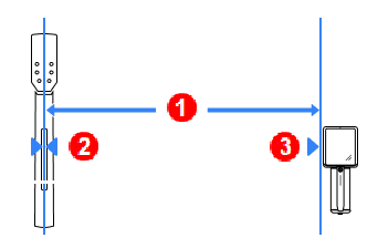
- Distance measured
- Center line of the transmitter perpendicular to the locator
- Side of the locator
(look for calibration marks)
The Ares locator will not allow depth readings until the transmitter has been calibrated and will display multiple warnings.
After selecting frequencies and confirming the bands reach the required depth, select Calibration to continue the transmitter setup.
Make sure that the transmitter and locator are connected with Bluetooth. Look for the Bluetooth connection icon in the status bar.
Falcon Users - In six quick steps, the Ares locator calibrates both bands and all power levels at once.
Follow the directions on the calibration screen, and then select Run calibration.
If calibration fails, follow the recommendations on the screen and then select "Recalibrate".
The locator will recalibrate and then guide you through an Above ground range (AGR) check.
To calibrate, recalibrate, or verify calibrations at any other time, on the Home screen, select "Jobsite setup", and then "Calibration".
For areas with strong background interference (noise), you can verify that the selected frequency bands will reach the depth needed by walking the intended bore path with both the locator and transmitter at the same distance apart as the depth of the bore.
This procedure takes two people, one holding the locator and walking the intended bore bath and the other holding the transmitter. At the end of the bore path, have the two people stand the same distance apart as the bore depth. They will walk the bore path, keeping parallel to each other. The locator operator watches the Locator mode screen for a strong and steady signal. Occasionally, the transmitter operator should change the pitch and roll of the transmitter, so the locator operator can verify the speed and accuracy of the readings on the locator. Note any locations where the data displayed becomes erratic or disappears.
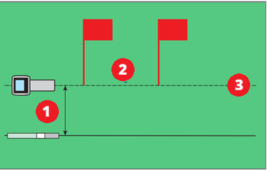
- Maximum bore depth
- Area of high interference
- Intended bore path
Suggestions for dealing with interference
If pitch/roll data becomes erratic or is lost, move the locator away from the interference source while staying in range of the transmitter. You can use HAG, change the power level, or try off-track locating.
Before You Start
Use the Roll Offset menu when the 12 o’clock position of the transmitter cannot be indexed to that of the drill head. Roll offset lets you program the locator to display the roll of the drill head rather than that of the transmitter.
On the Locate Mode screen, the roll indicator will change to a circle, and “RO” appears at the bottom left of the roll indicator.
From the Home screen, select Jobsite setup.
On the Locate mode tools screen, select Roll Offset.
Ensure the drill head is at its 12 o’clock position and that the transmitter is on. Note the roll value showing on the screen.
With the Set roll offset option highlighted as shown, select Set and enable to set the roll offset and then select Close to returns to the Jobsite menu, Roll offset (enabled) with the offset in degrees.
For example, 30o means the clock is 30o clockwise from the roll offset value.
Before You Start
An Ares locator locates the transmitter by detecting three specific "locate points" in the transmitter's magnetic field and displaying them as a ball or blue locate line on the screen.
- Front Locate Point (FLP) * shows where the transmitter housing is heading.
- Rear Locate Point (RLP) * in combination with the FLP allows you to determine where to find the Locate Line.
- Locate Line (LL) * shows the position of the transmitter beneath the locator when the locator is on the crosshair connecting the front and rear locate points.
By identifying these three points you can find the transmitter underground and know its depth and pitch.
DCI invented the Ball-in-the-Box user interface to make it quick and intuitive to find a locate point, speeding up drilling jobs: just move the locator so the ball moves into the box on the screen.
In a straight bore using only the FLP and projected depths can greatly increase the speed of locating.
Locate mode screen
- Pitch
- Transmitter data (attenuation warning, signal strength, temperature, and pressure)
- Telemetry, transmitter type, band, power mode, transmitter battery life, and locator battery life
- Drill housing clock (offset off)
- Box target (changes color to blue, if the ball is in the box and centered on both crosshair lines)
- Crosshair lines (blue, if the ball is centered on the line)
- Ball (blue and white if on a crosshair line or in the target box)
- Depth reading button (highlighted) and Tools button
To learn more about the Ball-in-the-Box locating, go to the Ball-in-the-Box Guidance article in the Bootcamp chapter.
To find the heading of the drill, first find the FLP * by centering the target ball in the box.
- The ball is the position of the nearest locate point (FLP or RLP). Mark the position on the ground of each locate point to determine the transmitter's heading.
- The crosshair lines change color to blue when the ball is centered on them.
- The box and the lines change color to blue when the ball is in the box and centered on both the crosshair lines. You have found a locate point.
At the FLP *, select Depth take a predicted depth and set the Reference Depth. The Locate Line (LL) * may not appear if this step is skipped. Mark the ground. Use the back arrow to return to the Locate mode screen.
Falcon Users - Ares always has a minimum Reference Depth of 5' (1.5m). As long as the locator is under 5' (1.5m), the LL will appear. If the depth is more, you need to take a reference depth at the FLP.
Falcon Users - The Ares locator does not display the R icon to indicate a Reference Lock, but taking a depth reading at the FLP is still required.
Find the RLP *to determine the direction you are travelling. Mark the ground.
At the LL, verify the locator is positioned on the crosshair line connecting the marks you made at the FLP * and RLP *.
The floating chevrons and blue bar guide you to the LL. by aligning the blue bar with the vertical cross hairs. When the Locate Line is on a crosshair line, the crosshair line turns blue and is in the box.
If the LP flips from one end of the locator to the other end without the LL line and chevron appearing, it is because the reference depth is to shallow. Move back to the FLP and take a depth. Adding HAG to the locator can also improve readings.
To view a depth reading, on the Locate mode screen, select the Depth button. Where you are on the bore path in relation to the locate points determines the type of depth reading you are taking.
Predicted depth - Take a depth reading at the FLP.
Depth at LL - Take a depth reading at the LL * between the FLP * and RLP *. The ball is on the Locate Line and the crosshair lines are blue. When you are confident of the reading, you can:
- Select Send Depth to send the reading to the connected remote.
OR
- Select Log point to add to the bore log and send to the remote at the same time.
Falcon Users - The Ares does not send a depth reading to the remote display automatically. Select "Send depth."'
Estimated depth - You can take a depth reading up to 35' (10.7m). past the FLP, as long as you stay on the crosshair line connecting the LL and FLP. You can log an estimated depth, but you will only capture the pitch or an blank rod. Estimated depth is not logged.
On the Depth screen, you can select Log point to add to the bore log.
To improve unstable depth/data readings, intermittent data or a "jittery" LL or LP, enable Max mode * from the Tools menu. You can log a data point while in Max mode. This may be the best way to log unstable data.
Select the back arrow to return to locating.
While you are in the Depth screen, do not move beyond the FLP. The locator may display a false LL. To correct this, return to the original locate point and exit the Depth screen. After recording and sending a Depth reading, it is a best practice to exit the depth screen and go back to the Locate mode screen. This will prevent a false LL.
An imaginary line ahead of the locator that indicates where the transmitter is heading. The FLP is where you take a predicted depth reading.
An imaginary line behind the locator, when combined with the Front Locate Line (FLP) ahead of the locator, and the Locate Line (LL) directly below the locator, allows the locator to calculate the position, depth, pitch, and direction of the transmitter.
An imaginary line directly under the locator.
Max Mode can stabilize roll/pitch data and depth readings when drilling at the transmitter’s range limit due to extreme depth or interference, which will vary by jobsite. See the Max Mode topic for use and important safety information.
The Target mode guidance method allows the locator to be placed ahead of the drill head and used as a steering target.
Use it to distance the locator from rebar that is causing signal interference and to drill where walkover locating is not possible.
Target mode is typically used on a straight drill path, not on a curved bath, terrain changes, or to correct a significantly off-course bore.
You can set a target depth and then use Target mode with left/right and up/down steering accurately up to 35 ft (10.7 m). After this range, you can still use left/right steering (remote steering) for the entire range of the transmitter.
Falcon Users - Setting a target depth is now optional and independent of sending steering information back to the remote display.
To turn Target mode on or off, from the Locate mode screen, select Tools, and then select Target mode.
On the Target mode screen, select the toggle to switch Target mode on.
To use a Target depth, * with the toggle switch set to on, enter the target depth.
Remote steering mode (optional)
If you set the target depth to zero, Target mode switches to Remote steering mode. The remote display will only receive left and right steering information and depth and predicted depth are turned off.
If the locator will be resting on the ground, toggle HAG in Target mode setting to off.
If the locator will be held off the ground or on a stand, select the off toggle to switch HAG in target mode on, select the height, and then select Save.
HAG in Target mode is enabled separately from HAG in Locate mode. Turning HAG off in one mode, does not affect the other mode. However, the height set is connected, setting height in Target mode changes the height in standard locating mode.
Falcon Users - Setting a target depth is now optional and independent of sending steering information back to the remote display.
On the Target mode options screen, confirm the settings and then select Apply to start Target mode.
Begin Target Steering
Place the locator on the drill path with its battery compartment facing the drill head. Target mode guides the transmitter to be at 0% pitch and inline with the locator's handle when it reaches the target depth beneath the locator.
Past 35' (10.7m), the depth prediction becomes less reliable. However, you can use left/right remote steering for the entire range of the transmitter by monitoring pitch.
If HAG is turned on for Target mode steering, the locator must be kept at the set height while locating. If you have to change the height or set the locator on the ground, turn off HAG in Target mode.
At this point, the drill rig operator uses the remote display and the transmitter data to drill to the target.
If at any time you need to change the depth or HAG, select Edit.
When the horizontal distance is almost the same as the current depth, move the locator farther out to continue steering in Target mode.
If you go past 35 ft (10.7 m) do not rely on the depth, predicted depth, and up/down steering information on the remote. Instead, monitor pitch data.
If the drill head passes beneath the locator, the left/right values on the Aurora become invalid. If the horizontal distance reaches zero, then all data past that point is incorrect.
To turn off Target mode, select Tools, and then Target mode, and select the on toggle to switch Target mode off.
A value programmed into the locator, so it can be positioned ahead of the transmitter housing and used as a steering target. The value programmed should be the desired depth of the transmitter when it reaches the point below the locator. If a locator is placed above ground level, such as to provide separation from interference, that height must be added to the target depth.
Note: If using a Falcon Compact Display, only left/right steering information is available. The locator used with the Falcon Compact Display must still have a target depth set. This target depth can be any value.
Before You Start
Use Max mode when pitch/roll data is unstable or missing to stabilize an unstable depth or locate signal when drilling at the limit of the transmitter's capabilities.
You can use Max mode during normal locating or while in Target mode and log a point. This may be the best way to capture unstable data.
On the Locate mode or Target mode screen, select Tools.
On the Tools menu, select Max Mode. The Max mode icon displays on the Locate mode or Target mode screens.
The number of blue bar indicates the reliability of the data. If the bars are gray, no data could be attained. This may take up to 30 seconds. If Max mode fails, go back to Locate mode and try Max mode in a new position.
The transmitter must remain motionless with no rotation or push/pull while in Max mode. If you need to move to a new location with less interference, exit Max mode and try it again at the new position.
To turn off Max mode and return to the Locate mode screen, select the back arrow.
To log the Mad mode- corrected data, select Log data point and log as usual. If there is no data, you can log a blank rod.
Before You Start
You can record real-time, rod-by-rod bore data from your locator and annotate the data with on-site obstacles and utilities.
After completing your bore, you can transfer the data files to your DigiTrak LWD app on your mobile device or Windows computer.
For the secure transfer of your files, the locator and the signed in user of the DigiTrak LWD App must be registered to the same company account on the myDCI portal. A myDCI company account is free and with an additional LWD Cloud subscription you can also store and share files with other registered users in your company.
For more information about myDCI portal, go to the myDCI Cloud Services manual in the DigiGuide App.
For the most accurate GPS data:
- Position the locator as high as possible. You could use a surveying tripod. The locator saddle is compatible with many tripod couplings. Remember to set the HAG for the tripod height.
- To take a depth reading, place the locator at the LL and step away from the locator. Do not move the locator for at least 5 seconds. This allows the locator to lock in the GPS signal. Select Log point.
Falcon Users - DataLogs are now called bore logs in LWD and Ares.
From the Home screen, select Jobsite setup.
You can also create a bore log from any Depth screen or the Max mode screen when you try to log a data point without an active log.
On the Jobsite setup screen, select Bore log and then select Create new log.
On the Create new log screen, you can rename the log and use Edit to change the default log parameters, before you select Create log.
On the LWD App, you can use GPS to mark this as the entry point.
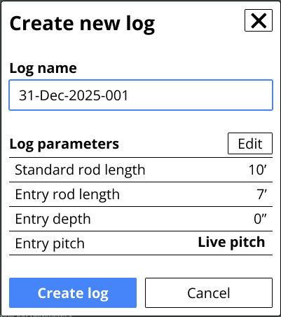
To create a new bore log, the locator needs either live pitch data from the transmitter or you need to edit the log parameters to enter the starting pitch (Rod 0) manually.
To change the default parameters for logging, go to the "Home" screen, select "Jobsite files", and then select "Log Defaults."
Falcon Users - The Ares does not collect the entry point with GPS.
On the Log created page, select Begin locating.
Because this is a new job, the locator displays the current settings, the active bore log.
To view these settings at any other time, from the Home screen select Jobsite setup.
The locator turns off bore logging when the locator is powered down. When you resume locating, you can resume the bore log or start a new one.
To log your first rod, select Begin locating.
Every time you take a depth reading, you will have the opportunity to log the rod and add any utilities, flags, pins, or notes. For more information, see the article Log data on an Ares locator in the DigiGuide App.
Before You Start
The LWD (Log-While-Drilling) feature on the Ares locator records data and transfers data to the DigiTrak LWD App on your mobile device or Windows computer to create customer-ready reports for your completed jobs. A free company account is required on the myDCI portal to transfer files between the locator and the LWD App. An additional LWD Cloud subscription on myDCI portal is required to share and store data in the cloud.
This article assume you have already started a new bore log job file.
For each rod, you can log:
- A depth and pitch reading for the transmitter
- A pitch only reading
- A partial rod
- A blank rod (no depth or pitch data is available, or the location is questionable)
- A utility on the bore path, including utility type, location, depth, and diameter
- Flags to mark landmarks or points of interest on the bore path
- Pins to mark landmarks or points of interest to the left or right of the bore path
- The offset to specify a horizontal distance that you are logging from a feature to the left or right of the bore path, such as a curb or fence
- The deviation to specify how far the drill head is deviating from the intended bore plan
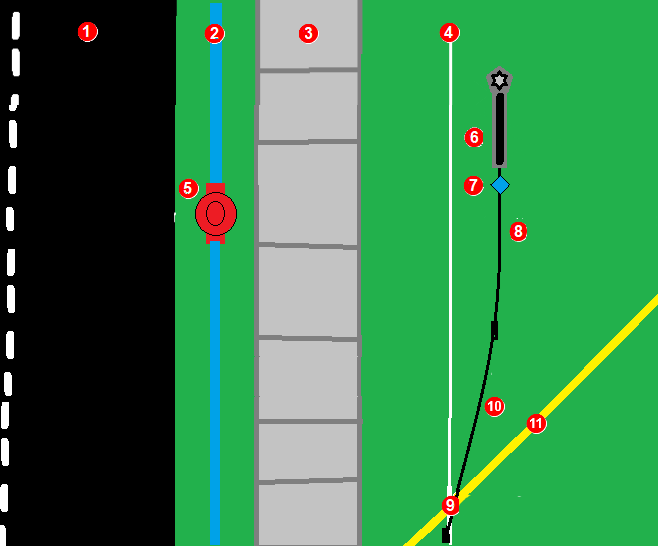
- road
- water line
- sidewalk
- planned bore path (white line)
- fire hydrant
- deviation to the right from planned bore path
- pin marking hydrant left of bore path
- rod 3 (black line)
- Utility marker for gas line on bore path
- rod 2 (black line)
- gas line (yellow line)
For the most accurate GPS location data, raise the locator on a stand, such as a surveying tripod. The locator saddle fits most standard tripods.
Falcon Users
LWD has not changed much since Falcon, but there are some differences to be aware of with LWD for Ares.
- The bore path's entry point (Rod 0) is recorded as soon as you create the DataLog (now called a bore log) file.
- Utilities are a separate marker from flags. Include clearance when you define the diameter.
- Pins and offset are left or right of the drill head with the drill rig behind you. This may be different than you were taught with a Falcon locator and LWD.
- Deviations are left or right of the intended bore path, with the drill rig behind you.
- Offsets are left or right of the bore head with the drill rig behind you.
- The bore log list is from top to bottom, with the most recent rod at the bottom.
On the Locate mode information screen, make sure that Bore log is on and that the correct job file is active, and then select Begin locating.
If you need to Create a new log, see the article Start a new bore log job file.
Drill the entry Rod 1 into the ground. Log a data point at the end of every rod. If using GPS logging should be done at the LL. If GPS is not important it can be quicker to log each rod at the FLP.
To record a data point and its annotations, position the locator at the LL (for GPS data), and select Depth.
If there isn't a signal, use Max mode * or take an estimated depth.
To record a blank rod or pitch only use the estimated depth mode if the LL or LP is not convenient. To add a utility or other annotation it is not necessary to be at the LL or LP, use the estimated depth mode.
For the most accurate GPS data, position the locator on the LL and step away from the locator. Do not touch the locator for at least 5 seconds. This allows the locator to lock in the GPS signal. After the short wait, you can take a depth reading and log the rod.
Before you log the depth and pitch as a data point, log any flags, pins, or utilities. Any flag, pin or utility MUST be recorded before you log the Depth and Pitch. Skip this step and add the notations. Deviations and Offsets are saved with rod depth and pitch.
On the Depth screen, select Log data point.
If there isn't an active log, you can create a new log or resume an existing log.
The Log point screen displays the data to log. If there is no depth or pitch data available, log a blank rod or edit the log parameters to log a partial rod.
Before saving the data, select the three-dot icon to open the Log parameters screen and edit the parameters and add any additional information, such as partial rods, utilities, flags, or offsets.
To log a utility for this rod
- On the Log Point screen, under Log other, select Utility.
- On the Utility screen, enter the details:
- type of utility (phone, water, fiber, etc.)
- location of the utility from the start of the rod (the LL of the previous rod)
- depth (option to measure from top, center, or bottom of the utility to the ground surface)
- diameter of the utility including the clearance that you want to use
- Select Save.
The utility is logged, but not the rod. - On the confirmation screen, select Go Back to return to the Locate mode screen, and add additional annotations or log the depth and pitch for the rod.
To log a flag or pin for this rod
- On the Log parameters screen, select Flag if the point of interest is on the bore path.
- OR -
Select Pin if the point of interest is on either side of the bore path. - On the detail screen enter the position of the flag or pin along the rod. For pins, you should also note how far the point of interest is from the bore path to the right or left. Measure from the point of interest to the center line of the locator.
- Select Save.
The flag or pin is logged. - On the confirmation screen, select Go Back to return to the Locate mode screen, and add additional annotations or log the depth and pitch for the rod.
Flags and pins are named and logged sequentially. You can edit the bore log in the LWD App to give it a more descriptive name.
Offset can be turned on or off and adjusted to different distances at any rod number. For example, a curb offset may start at rod 7 at a distance of 3 m left and end on rod 27. A new offset of a road edge may start at rod 50 at 1.5 m right and last to the end of the bore.
To use an offset for this rod
Specify a given horizontal distance you intend to maintain from a
feature beside the bore path, such as a curb, guardrail, or surveyed path.
- On the Log Parameters screen, select the distance from the bore path to the feature you wish to follow.
- Select if the offset is to the left or right of the intended bore path.
- Select Save.
The offset is logged. - On the confirmation screen, select Go Back to return to the Locate mode screen, and add additional annotations. If you select "End log" or the locator times out before you log the rod, the annotations will not be saved with this rod.
To record a deviation from the planned bore path for this rod
You mark how far the drill head is deviating from the intended bore path.
- On the Log Parameters screen, select the distance from the planned bore path.
- Select if the deviation is to the left or right of the intended bore path facing away from the drill rig and the distance from the center of the locator to the planned bore path.
- Select Save.
The deviation is logged. - On the confirmation screen, select Go Back to return to the Locate mode screen and add additional annotations. If you select "End log" or the locator times out before you log the rod, the annotations will not be saved with this rod.
A best practice to confirm exact position of an LWD log point is to always have deviation ON and set to 0. Change the deviation when the drill head is not at zero deviation.
To log a partial rod
- On the Log parameters screen, select how much of the rod to record (1/4, 1/2, 3/4, or full)
- Select Save to return to the Log point screen.
The button is updated with the Rod number with the partial rod as a decimal. 5.5 is the half of the 5th rod.
If a utility is added to a partial rod. Measure the distance from the start of the second half of the rod.
You cannot add details to a rod such as utility, flags, and offsets after you log the rod. Add the notations one at a time before logging the rod (full or partial).
After you have selected and entered all of the data for this rod, including if it is a full or partial, select blue bar with the rod number to log the rod.
All annotations entered will be applied to this rod.
The Rod logged confirmation page displays the data logged. Click Go back to return to Locate mode and continue locating.
If you select "End log" or the locator times out before you log the rod, the annotations will not be saved with this rod.
To view the log file, go back to the "Home" screen and select "Jobsite files", and then select the jobsite file. You can view the log summary or the rod-by-rod detail. To make corrections to a completed log, transfer the log file to the LWD DigiTrak App.
To create a new log, you need to end the active log. You can do that from any LWD screen with an End log button. The active log will also end when the locator is powered off.
To delete a rod
If one or more rods were pulled back or accidentally recorded twice, you can delete the most recent rod entry in the bore log.
- On the Log point page, select View full log.
- On the Log detail screen, select the Rod detail tab
- On the bottom of the screen, select Delete rod.
You can only delete the most recent rod entered. - On the confirmation screen, select Delete. This cannot be undone.
On the Rod detail screen, you can delete additional rods one at a time from the most recent entered.
Make sure that the number of rods deleted match the number of rods pulled back.
Max Mode can stabilize roll/pitch data and depth readings when drilling at the transmitter’s range limit due to extreme depth or interference, which will vary by jobsite. See the Max Mode topic for use and important safety information.
On the Ares locator, from the Home screen, select Jobsite files, and then select Transfer Files.
To transfer a bore log file to the LWD App, you need the LWD App on a Windows computer or smart device and a free company account on the myDCI portal. To store files on myDCI or share files, you also need an LWD Cloud subscription.
Falcon Users - DataLogs are now called bore logs.
- To transfer all of the completed files, select Transfer files.
- To transfer a specific completed file, select the file, and then on the job file detail screen, select Transfer.
On the locator Transfer log file screen, click Ready to pair to continue.
Open the DigiTrak LWD App on your mobile device or computer (with Bluetooth) and tap Add Bore log.
Make sure that Bluetooth on the device or computer is on.
Select the Ares locator from the list of devices.
If you do not see the Ares locator on the list and there are no issues with Bluetooth on either the device or locator, make sure that you have the current version of the LWD App. You may need to go to the App store and reinstall or update the DigiTrak LWD software.
After the transfer is complete, you can close the App confirmation window and the App or continue to work in the App by viewing the log details or list of files.
For more information about working with LWD files in the LWD app to create reports, upload to the LWD Cloud, or share data, go to the DataLog and DigiTrak LWD manual.
Before You Start

Switching frequencies on the transmitter may provide better data, better depth, and/or better locate results as interference conditions change. After changing the active frequency on the transmitter downhole using this procedure, you also need to change the locator's active frequencies match the transmitter's active band to regain signal.
Disable Roll Offset (if enabled). See the Set and enable Roll offset article for instructions.
If you do not have a live clock, you can also use the RRS3 roll sequence to change the transmitter's active frequencies.
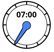
Roll the drill head clockwise to approximately 10 ± 1 clock position. Wait 10-20 seconds
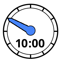
Roll the drill head clockwise to approximately 2 ± 1 clock position. Wait 10-20 seconds

Roll the drill head clockwise to approximately 7 ± 1 clock position. Wait 10-20 seconds
The transmitter changes bands and the data is not displayed on the Locate mode screen.
On the locator, change the active frequencies, and then re-enable Roll Offset, if needed.
Before You Start
Use this roll method to change Active bands below ground if you do not have a live clock position.
1. Remain at any clock position (CP) for at least 40 seconds to clear all timers.
2. Make a reference mark on the drill string.
Complete one full clockwise rotation (±2 CP) of the reference mark within 0.5–30 sec., then wait 10–20 seconds.
Repeat step 3 two more times, for a total of three rotations (RRS3).
After the third rotation, leave the drill string at rest for a total of 60 seconds, after which the transmitter changes frequency.
On the locator, change the active band and return to the Locate mode screen and verify the transmitter data is displayed.
If any rotation is not completed within the prescribed time, or if any rotation continues for more than one full revolution, the transmitter frequency change is canceled.
Before You Start
Switching bands on the transmitter may provide better data, better depth, and/or better locate results as interference conditions change. After changing the active band on the transmitter downhole using a 10/2/7 roll sequence, you also need to change the locator's active band match the transmitter's active band to regain signal.
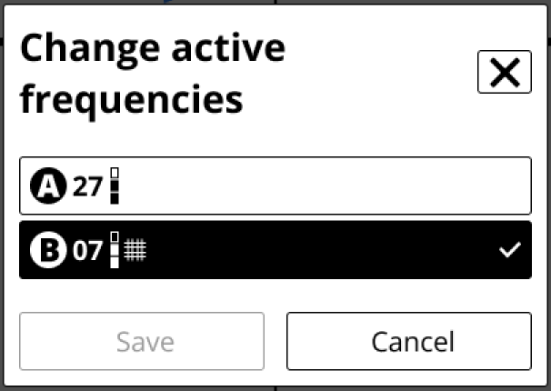
On the Locate mode or Target mode screen, select Tools.
On the Frequencies screen, select Change active frequencies to toggle between band A and band B. The active band has a checkmark.
You can confirm the locator is receiving data on the Locate mode screen.
To go to the Locate mode screen, click the Jobsite setup back button, and then Home screen back button, and then the Locate mode button.
If the transmitter's Bluetooth is unavailable or unstable, the transmitter band change will fail with an error. However, the locator will change the active band and regain signal on the Locate mode screen.
Falcon Users - This procedure replaces the toggle right shortcut to change frequencies.
Before You Start
All DCI transmitters have a standard Sleep mode to save battery life when the transmitter is not being actively used.
To wake up a DigiTrak SuperCore or Classic-Core transmitter
Quickly rotate (more than 20 RPM) the drill head and transmitter at least a quarter rotation/90°.
Falcon Users - Ares transmitters require a faster wake-up roll than a Falcon transmitter.
Check the Locate mode screen to verify the transmitter is sending a signal.
DigiTrak Ares Locate Mode screen
To power off the locator, on the Home screen, select the power icon.
Remove the battery and inspect its contacts and those inside the battery compartment for corrosion and debris. Clean and charge as needed.
Wipe the locator clean. Use only an abrasive-free cleaner and soft cloth to clean the screen.
Do not pressure wash.
Store the battery and locator in the original system carry case safe from impact, moisture, and excessive temperatures.
Do not store the battery in the battery charger or locator.
Storage and transportation temperature must remain within -40° to 149°F (-40° to 65°C).
Remove the transmitter from the drill head.
Wipe the transmitter clean so dirt doesn’t enter the battery compartment or accumulate on the battery cap threads.
Remove the transmitter batteries to power it off.
The transmitter records active run-time for warranty purposes. Sleep mode is not counted.
Inspect the battery compartment, springs, cap, O-ring, battery adapter, and threads for debris. Clear any debris and replace the battery cap.
Use conductive lubricant on the threads if the battery cap is difficult to turn.
Store batteries so they do not contact metallic objects or terminals of other batteries.
Store the transmitter in the original system carry case where it will be safe from impact and excessive temperatures.
Storage and transportation temperature must remain within 40° to 149° F (-40 to 65 °C).
Before You Start
You can transfer a complete or incomplete bore log file from the locator to DigiTrak LWD App for editing, annotating, and storing. A free company account on the myDCI portal is required to transfer files between the locator and the LWD App. An additional subscription for LWD cloud is required to store and share bore logs.
Log-While-Drilling (LWD) bore log files are stored on the locator indefinitely, but DCI recommends deleting files after they have been transferred to the LWD App.
On the Home screen, select Jobsite files.
On the Jobsite files screen, you can:
- View the log summary and view or edit log details for a bore log file
- Delete one or more files
- Transfer one or more files to the DigiTrak LWD App
To view log summary and view or edit details for a job file
- Select the job file, the file opens automatically.
- The Summary tab displays the log history, details, and parameters.
- The Log detail tab displays a rod-by-rod chart, pitch, depth, distance, and any utilities, pins, and flags.
- To view or edit the specific details of a rod, select the rod. You can edit any of the rod details except rod number, depth, or pitch.
From this screen you can also, transfer the file to the LWD App, make this file the active log, or delete the file.
Deleting a log file cannot be undone, and you cannot reload a file transferred to the LWD App.
On the Ares locator, from the Home screen, select Jobsite files, and then select Transfer Files.
To transfer a bore log file to the LWD App, you need the LWD App on a Windows computer or smart device and a free company account on the myDCI portal. To store files on myDCI or share files, you also need an LWD Cloud subscription.
Falcon Users - DataLogs are now called bore logs.
- To transfer all of the completed files, select Transfer files.
- To transfer a specific completed file, select the file, and then on the job file detail screen, select Transfer.
On the locator Transfer log file screen, click Ready to pair to continue.
Open the DigiTrak LWD App on your mobile device or computer (with Bluetooth) and tap Add Bore log.
Make sure that Bluetooth on the device or computer is on.
Select the Ares locator from the list of devices.
If you do not see the Ares locator on the list and there are no issues with Bluetooth on either the device or locator, make sure that you have the current version of the LWD App. You may need to go to the App store and reinstall or update the DigiTrak LWD software.
After the transfer is complete, you can close the App confirmation window and the App or continue to work in the App by viewing the log details or list of files.
For more information about working with LWD files in the LWD app to create reports, upload to the LWD Cloud, or share data, go to the DataLog and DigiTrak LWD manual.
Go to Settings, scroll up or down and under System, select About this locator.
On the Help screen, select System information.
System information includes:
- Serial #
- Region
- Part number
- First day of use
- Run time
- Current system time
- Edit current time - Takes you to the Date and time screen.
- Bluetooth address
- Bootloader
- Image
- DigiRadio
- DSP
- Application
- 3rd party licenses (Select to view)
Before You Start
You can download software updates with new features and upgrades for your DigiTrak Ares locator over Wi-Fi, including stable mobile hotspots. The locator automatically disconnects from Wi-Fi after the update is complete.
For more information about connecting to Wi-Fi on your locator, see the article Connect to Wi-Fi.
Some software updates are optional. However, some features and functionality will not be available without the current software. If a software update is available, a message is displayed on the equipment page on the myDCI portal. You can also check for updates in Settings.
From the Home screen, scroll down and select Settings.
On the Settings page, under System, select Software updates.
Select the network to use and then enter the password using the D-pad and trigger. The locator will remember the password the next time you connect.
If a Wi-Fi network is hidden and doesn't broadcast their SSID, you can still connect to these networks if you know: 1) the network name or SSID 2) the type of encryption used by the network 3) the network password.
After connecting, the locator checks for updates.
- If the locator software is up-to-date, the current version is displayed, with a message. Select Close to return to the Settings menu.
- If the locator software needs an update, click Download and Install, and then select Begin update. When the update is complete, the locator will restart.
- If the update fails, contact DCI Customer Support.
Do not turn off the locator or switch screens until the update is complete. Time to update will vary depending on connection speed and may take several minutes. Make sure the locator battery is at least half full, so that the update is not interrupted.
Before You Start
A stable wi-fi connection is required to check for software updates. Known networks are the Wi-Fi networks that your device has previously connected to and saved to use in the future, including passwords. You can "forget" networks you no longer want to use and remove them from the list.
If the password has changed, you may need to re-enter it or forget the saved network and reconnect and re-enter the password.
Go to Settings, scroll down and under Networks, select Wi-Fi
Under Known Networks, select the network to forget and remove from the list.
Select Forget this network, and then select Forget.
Close the Wi-Fi screen to return to the Settings screen.
Before You Start
For jobsites with challenging interference, an experienced driller can select the frequency bands manually. After setting the expected bore depth, you will walk the proposed bore path and then compare achievable depth of the signals against each other. Select a potential frequency band as pending, select the signal power level *, add rebar if needed, and then continue to walk the bore path and make comparisons and select a second band or replacing a band with a better performing one.
After you have determined that you have the two best frequency bands for the job set to pending, you can load them into the transmitter via Bluetooth and, after calibrating both bands and power levels at the same time, start locating.
Manual selection also offers a Quick Pick option that suggests the two best performing frequency bands. If after walking your bore path, you decide the two suggested frequency bands work the best for the job, you can load both at once.
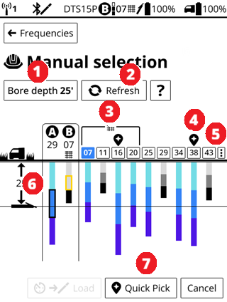
- Bore depth button. Changes the bore depth line.
- Refresh. Rescans for all new frequencies but keeps the pending frequencies.
- Current selected frequencies to load (Pending have a clock icon above it).
- Rebar frequencies (07 (selected), 11, 16, 20). for passive interference.
- Quick Pick icon. Suggested frequencies for quick loading.
- Scan options. Use to clear noise spikes and reset depth bar colors.
- Desired bore depth and depth line.
- Quick Pick. Loads frequencies marked with Quick Pick icon.
Falcon Users - Manual frequency selection in Ares may seem similar to Frequency Optimization in Falcon with similar steps and screens. An obvious difference is that after setting a bore depth, the graph displays the depth reached by each band instead of the noise. The chart also displays your maximum bore depth to give you confidence that the selected bands will do the job. Up and Down have been replaced with A and B. No more keeping track of how the batteries are installed. With the new Ares SuperCore transmitter and Classic-Core transmitter you can use both wideband and rebar in the same transmitter.
On the Home screen, select Jobsite setup and then Frequencies.
On the Frequencies screen, select New frequencies, and then Manual selection. Read the online help screen, and then select Begin environment scan.
During the environmental scan, the transmitter is in standby mode with no signal. Before loading frequencies, if the locator is in Bluetooth range (10-13 ft (2-3 m)), it will wake up the locator. If loading frequencies fail, try a wake up roll on the transmitter and try to load frequencies again. If the situation persists, contact DCI Support.
Select Bore depth and enter the deepest bore depth expected for this job. The bore depth line will adjust. Any bands that cannot reach that depth will turn shades of grey and bands that can reach the depth are shades of blue. The different shades represent the power levels with the selected power level outlined.
Falcon Users - With the Ares Manual selection, you can select a band and set to pending, change the bore depth and go to another area, select "Refresh" to rescan.
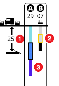
- Bore depth
- A is set to band 29 at standard power (black outline). The depth bar is blue and reaches past the bore depth
- B is set to band 07 at standard power (yellow outline) with rebar. The depth bar is grey because it does not reach the bore depth.
If at any time during a scan, a band cannot reach the bore depth, it will turn grey. You can select the scan options icon (three vertical dots) to the right of the band numbers to reset the chart.
As you walk the bore path and come to areas of high interference or other drilling challenges, you can compare the displayed bands:
- The suggested Quick Pick bands
- Rebar bands
- Current bands assigned A or B.
When you find a new band that you want to use, select the band number. The Configure screen opens.
On the Configure screen, you can:
- Assign the band to either A or B.
- Select the transmitter power level *.
- Add a rebar tone to help with passive interference *.
The pending area displays any previously selected or loaded bands for easy comparison with new bands, and you can replace one or both if you find a better performing band.
Falcon Users - Unlike with Falcon transmitters, all the power levels will give you the fastest data speed.
To add rebar
In the area of the bore where you think you will have problems with passive interference/rebar, scan the area again. The locator picks the best Sub-K frequency for band 0.3, 0.5 and 0.7 kHz.
- On the Add rebar screen, select the Bore depth at rebar.
- Compare the signal for the depth tone options.
- Select the Rebar Depth tone.
- Select Save.
To fine tune the frequency bands, go to the area with rebar and rescan.
Adding a rebar depth tone reduces the depth range of the selected band.
On the Configure screen, select Set pending to continue.
On the Manual selection screen, you can continue to walk the intended bore path, changing the bore depth, rescanning frequencies with Refresh, and selecting bands as the conditions change.
Bands with a rebar noise tone have the rebar icon.
The bands marked with the "Quick Pick" icon may not always be the best bands for a specific location, but are the best bands for the entire bore path walked so far.
When you are satisfied with the pending bands or quick picks, select Load. This loads the pending bands for comparison with the current bands.
On the Review and confirm screen, you can compare the pending bands with the current bands, and then either go Back to scan or continue selecting bands.
When you are satisfied with your selection, return to Bluetooth range of the transmitter and select Load to pair the new bands with the transmitter.
Before you load the pending bands, walk the intended bore path again, or at least return to the areas with the most intereference or deepest part of the bore to confirm that that pending bands will reach the bore depth.
staying with the locator within Bluetooth range (13-15 feet (3-4 m)) of the transmitter, confirm the Bluetooth connection on the status bar, and then select Calibration to continue.
For more information, go to the Calibrate article in the Jobsite Setup chapter.
Calibration is required anytime you change your drill head or select new frequencies, including adding or removing rebar from one or both saved bands.
The Ares SuperCore transmitter has three power modes to balance signal strength and battery life. Usually, high signal strength reduces battery life and low signal strength extends battery life.
Sources of passive interference include metal pipes, rebar, trench plates, chain-link fences, vehicles, saltwater.salt domes, conductive earth, such as iron ore.
You can view the transmitter's information on the status bar on all of the main locator screens.
- Active transmitter's model
- Active band and frequency
- Power mode
- Battery charge level
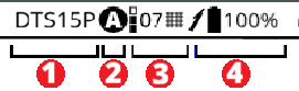
It a manual frequency change was made using a roll sequence underground, the status bar may not display the current band.
The Transmitter details pages provide additional information, such as run-time, warranty, software version, Bluetooth details, and warranty.
If the transmitter is not connected to the locator with Bluetooth, the details page displays the last known status and information. Information will be updated when the transmitter reconnects.
From the Home screen, click Jobsite Setup, and then Transmitters.
In the transmitter list, select the Details icon beside the transmitter you want information about.
On the Transmitter details menu, select the information you want to view for the active transmitter.
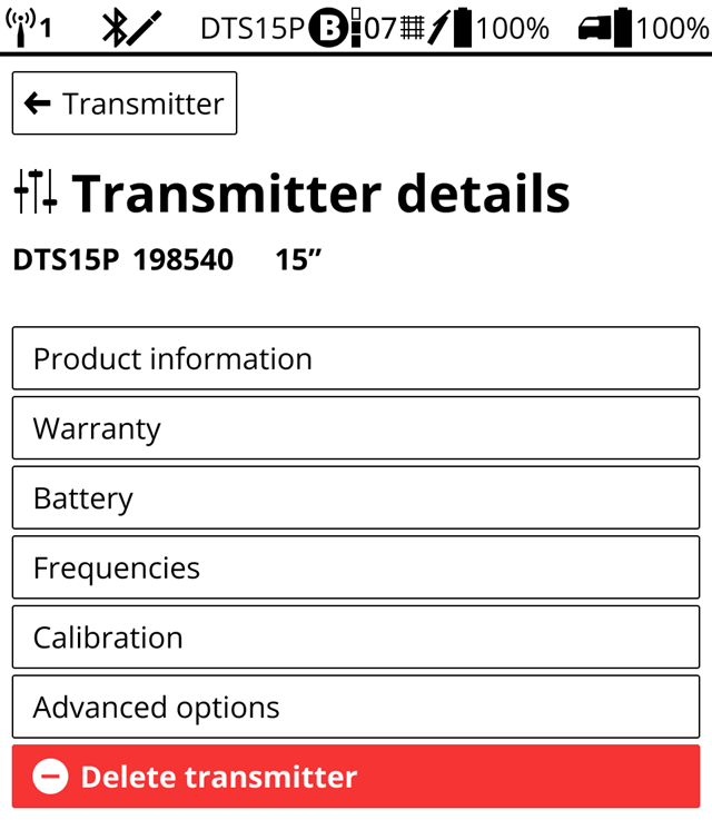
Falcon User - You can view the last stored information on any transmitter that the locator has paired with. The current active transmitter has a check mark. If the active transmitter is connected by Bluetooth, the information is up-to-date.
DigiTrak transmitters (Tx), with the exception of DucTrak, have temperature overheat indicators (temp dot) on the front end cap.
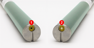
- Black temp dot
- Normal white temp dot
The temp dot has an outer yellow ring with a temperature-sensitive 1/8" white dot in the center. If the center temp dot is black, the transmitter has been exposed to excessive heat over 220°F (104°C) and should no longer be used and the warranty is voided.
The DCI Warranty does not cover any transmitter that has been overheated or had the temp dot removed.
SuperCell-R batteries also has a temperature dot. The battery will shut off if the battery temperature rises above 185°F and the temperature dot on the battery turns black. The transmitter may not record temperatures above this limit. A black or grey dot will cancel the warranty.
DigiTrak transmitters (Tx), with the exception of DucTrak, have an internal digital thermometer. The normal below ground temp range is 63° to 104° F. The Tx temperature displays on the bottom of the locator screen and remote display screens.
Suspend drilling when temperatures increase rapidly. Temperatures above 111° F are not typical.
As the transmitter (Tx) temperature increases above 61° F, the locator and remote emits warning beeps and the temperature icon changes on the locator or remote display.
Tx temp: 61° to 97° F
Warning tones: Double beep (beep-beep) for every 7° F increase.
Watch for an upward trend in temperatures.
Tx temp: 104° to 111° F
Warning tones: Two double beeps (beep-beep; beep-beep) for every 7° F increase.
Cool the transmitter.
Tx temp: 118° to 133° F
Warning tones: Three double beeps (beep-beep, beep-beep, beep-beep) for every 7° F increase.
Cooling is critical to avoid irreversible damage.
Tx temp: 140° F and above (icon flashing)
Warning tones: Three double beeps (beep-beep, beep-beep, beep-beep) for every 20 seconds on the locator and 5 seconds on the remote display.
The transmitter has been exposed to dangerous drilling conditions. Temperatures above 185° F may cause irreversible damage to the transmitter.
SuperCell-R batteries also has a temperature dot. The battery will shut off if the battery temperature rises above 185°F and the temperature dot on the battery turns black. The transmitter may not record temperatures above this limit. A black or grey dot will cancel the warranty.
The transmitter records the maximum temperature that it has been exposed to. Use the Transmitter Info screen to view this information. See "Get Transmitter Info" for steps.
Before You Start
All DCI transmitters have a standard Sleep mode to save battery life when the transmitter is not being actively used.
In addition to the standard Sleep mode, the DigiTrak SuperCore and Classic-Core transmitters have an optional SnooZe that turns the signal off when the transmitter is actively drilling down-hole to help extend battery power.
Standard mode versus SnooZe
Standard mode: If the transmitter does not rotate (less than 5°) for more than 15 minutes, it will turn off the signal. When drilling resumes and the driller performs a fast wake up roll, the transmitter "wakes up" and the signal resumes. With a normal workday, a battery charge can last several days.
SnooZe mode
For longer bores with DigiTrak SuperCore and Classic-Core transmitters, turn on SnooZe mode to extend battery life by several days or weeks by preventing the transmitter from sending a signal. While the transmitter is down-hole, a specific roll command can reactivate the signal to check for depth and pitch and then deactivate the signal for as long as needed. Though this feature was designed as a back-up for wireline users to verify a walkover locate it is often used when a second tandem transmitter with fresh battery with a full charge is required in a long bore.
SnooZe mode can only be turned on and off while above ground and connected to the Ares locator with Bluetooth. Turning off SnooZe mode returns the transmitter to Standard mode and the 15-minute with no rotation Sleep mode.
The transmitter tracks how long it is stationary and not rotating.
Standard mode with SnooZe off
- Up to 15 minutes of no rotation, the transmitter is sending a sends a signal.
- After 15 minutes of no rotation, the transmitter stops sending a signal. This is Sleep mode. Use a fast wake up roll to regain the signal.
SnooZe On and signal on
- Up to 15 minutes of no rotation, the transmitter is sending a sends a signal.
- After 15 minutes of no rotation, the transmitter stops sending a signal. This is Sleep mode. Use a quick wakeup roll to regain the signal.
- After 75 minutes of no rotation, the transmitter is not sending a signal, if rotation restarts, the signal will stay off. Use a quick wakeup roll and an RRS4 roll to regain the signal.
- To turn off the signal with rotation, use an RRS4 roll.
SnooZe on and signal off
- No signal with or without rotation.
- To turn signal on, use a quick wakeup roll and then a RRS4 roll
Tracking runtime
When the transmitter is not rotating and goes into Sleep mode (after 15 minutes no rotation), run time is not tracked. Run time is tracked at all other times, including in SnooZe (signal or no signal) and the 15 minutes before the transmitter goes into Sleep mode.
A transmitter in Sleep mode cannot accept any commands, either with Bluetooth or roll sequences, until a fast wakeup roll is performed.
M-Snooze-Enable Z-mode and turn signal on or off on an Ares locator
The transmitter must be within Bluetooth range of the locator and not in sleep mode to enable or disable SnooZe.
- On the Home screen, select the transmitter type.
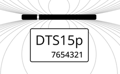
2. On the Transmitter page, select the Details button.
3. On the Transmitter details screen, scroll down and select Advanced options.
4. On the Advanced options screen, toggle SnooZe On. The SnooZe status option appears.
WhenSnooZe is on, you can turn the signal on or off above or below ground.
- Above ground (and Bluetooth is available), use this screen. Signal on or off.
- Below ground, use an RRS4 roll *.
When SnooZe is enabled with muted signal, you cannot use any change band methods, such as 10-2-7, RRS3, or tilt-method.
Before You Start
The Repeated Roll Sequence 4 (RRS4) turns the signal of a transmitter in SnooZe on and off. The sequence can be completed manually or assisted by the Aurora display's XR App.
- Execute a fast wakeup roll to verify that the transmitter is not in Sleep mode.
- Make a reference mark on the drill string at the current clock position.
When SnooZe mode is off, the RRS4 roll is ignored.
Start the RRS4 roll sequence.
- Hold the transmitter reference mark positioned, hold the transmitter stationary for at least 40 seconds.
- Complete one full clockwise rotation (±2 clock position) of the reference mark within 30 seconds, then hold clock position for 15 seconds (± 5 seconds).
- Repeat the rotation three more times, for a total of four rotations (RRS4).
After the fourth rotation, you should see the signal return within 60-80 seconds. If the signal does not return, repeat the RRS4 steps again.
Best practice. If there are a lot of rods in the ground, pull the last rod partially back, and rotate the rod several times to make sure the rod can rotate easil without "rod wrap."
Count rotations carefully. If there is a signal, three rotations (RRS3) will cause a band change. To confirm the mode change was successful, on the locator check both the Up and Down band. For more information, search the DCI DigiGuide App.
Before You Start
An active Bluetooth connection on the locator is required to pair with the transmitter for loading frequencies, as well as connecting to a smart device for the Log While Drilling (LWD) App.
Bluetooth is always enabled when the locator is on, except when the locator is actively scanning frequences for during jobsite setup. If you cannot pair with a transmitter or the LWD app, check the locator status bar for the Bluetooth error icon.
Try one or more of these steps to solve the problem.
Bluetooth is available but unconnected.
An intermittent connection
If the transmitter does not maintain a Bluetooth connection at 10foor (3m) range, check that the drill head slots are clear of mud and debris. Elevating the housing above the ground will also increase the Bluetooth range.
Power cycle the locator
With the transmitter on, power off the locator. Wait several seconds and then pull the trigger for 2-3 seconds to restart the locator.
If the transmitter LED light turns blue, the transmitter and locator are connected. You can also check that data is being received on the locator.
Delete the transmitter from locator and re-add it
a, On the Home screen, select the transmitter icon.
b. On the Transmitter page, select the Details icon.
c. Select Delete transmitter, and the select Delete.
d. The locator will reconnect with the transmitter and add it to the list of transmitters. Select the transmitter to re-add it.
Reset Bluetooth on the locator
- From the Home screen, select Settings.
- On the Settings page under Network, select Bluetooth.
- Select Reset Bluetooth.
If the issue continues, contact DCI Customer Support.
Product ID: DR-ARES
Model number: AEO2
Receiving frequencies: 0.33 to 45.0 kHz
Accuracy 1: ±5% of depth reading
Telemetry channels 2: 4
Telemetry range 3: Up to 3000 ft (900 m)
Target mode range 4: 35 ft (10.6 m)
L/R steering range: Range of transmitter
Power source: Lithium-ion battery pack
Battery life: 8–12 hrs
Functions: Menu-driven
Controls: Four-way D-pad and trigger
Graphic display: Full-color LCD
Audio output: Beeper
Voltage, current: 14.4 VDC nominal, 390 mA max
Operating temperature: -4 to 140° F (-20 to 60° C)
Dimensions: 15 x 5.5 x 12.7 in (38.1 x 13.97 x 32.26 cm)
Weight (with battery): 8 lb 14 oz (4.02 kg)
Compatible transmitters: DTS15p, DT15p
Compatible displays: Compatible remote displays: Aurora
Warranty period: One year from date of purchase
(1) Over specified depth range for each transmitter model.
(2) Local telemetry frequencies and power levels available at digital-control.com.
(3) Telemetry range is dependent upon the remote display and optional external receiving antenna.
(4) Requires an Aurora Display.
COMPLIANCE
This equipment complies with the following: Part 15 of the Rules of the FCC; Innovation, Science and Economic Development Canada's license exempt RSS(s); ACMA Radio Communications Standard (2021) as found in ACMA Radio Communications Equipment General Rules (2021). Operation is subject to the following two conditions: (1) this equipment may not cause harmful interference, and 2) this equipment must accept any interference received, including interference that may cause undesired operation.
L’émetteur/récepteur exempt de licence contenu dans le présent appareil est conforme aux CNR d’Innovation, Sciences et Développement économique Canada applicables aux appareils radio exempts de licence. L’exploitation est autorisée aux deux conditions suivantes : 1. L’appareil ne doit pas produire de brouillage; 2. L’appareil doit accepter tout brouillage radioélectrique subi, même si le brouillage est susceptible d’en compromettre le fonctionnement
DCI is responsible for FCC compliance in the United States. Changes or modifications to any DCI equipment not expressly approved and carried out by DCI will void the user’s Limited Warranty and the FCC’s authorization to operate the equipment.
Digital Control Incorporated
19625 62nd Ave S, Suite B103, Kent WA 98032;
Phone +1.425.251.0559 or +1.800.288.3610 (US/CA).
To find a regional office, tap Contact on the DigiGuide menu bar or on the last page of the PDF version of the DigiGuide.
The DR-ARES contains a Bluetooth Smart Ready module, model #BT121, FCC ID QOQBT121. BT121 operates at a frequency of 24.02- 2480 MHz. The maximum output power is 0.013 W.
DigiTrak locators are classified as Class 2 radio equipment per the Radio Equipment Directive 2014/53/EU and may not be legal to operate or may require a user license to operate in some countries. For a list of restrictions, see the article, “Product CE Declarations of Conformity” can be found at www.digital-control.com or upon request to productcompliance@digital-control.com.
Patents - https://www.digital-control.com/patents/
Trademarks - https://www.digital-control.com/trademarks/
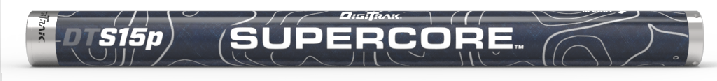
Product ID: DTS15p
Description: Ares SuperCore transmitter
Model number: RTP
Label color: Dark blue
Features
- Wideband
- Sub-kHz Rebar
- Fluid Pressure
- Multipower
- Bluetooth
- Extended long-range
- Extended battery
- SnooZe mode
- Assembled in the USA
Compatible locator: Ares
Transmitting frequencies:
- Wideband: depth and data 4.5kHz to 45kHz; 8100 frequencies
- Sub-k: Depth 330Hz to 750Hz, Data 4.5kHz to 23.5kHz; 3884 frequencies
Length/diameter: 15in/1.27 in (38cm/3.23cm)
Clock resolution: 24
Depth/data range by power level (1)(2)
Wideband
- High: up to 160 ft (49 m) / 280 ft (85 m)
- Standard: up to 140 ft (43 m) / 220 ft (67 m)
- Low: up to 100 ft (30 m) / 170 ft (52 m)
Sub-kHz Rebar
- High : up to 80 ft (24 m)/250 ft (76 m)
- Standard : up to 75 ft (23 m)/200 ft (61 m)
- Low : up to 50 ft (15 m)/160 ft (49 m)
Battery type:
DCI SR40 SuperCell-R Li-Ion Rechargeable 7.2v
(Requires DigiTrak Li-Ion charger kit)
See Technical Specification for details.
Battery life by power level:
- High: up to 10 hrs
- Standard: up to 35 hrs
- Low: up to 100 hrs
- Sleep mode: <1700 hrs
Pitch and fluid pressure resolution
- Pitch - Standard: ±0.1 % at full range
- Pressure- Standard: 1 psi at 0 - 250
Temperature readout/resolution: -4F to 219F @ 7F res (-20C to 104C @ 4C res)
Voltage/current: 7.2V / 5.33Ah Max
Weight (without batteries): 1.72 Ib (780 gr) / 1.330 Ib (603 gr)
Operating environment
- Temperature 220°F (104°C)(3)
Warranty period:
- 3 years or 500 hours depending on which comes first.
- Warranty canceled if temp dot is grey/black at temperatures above: 220°F (104°C)
(1) Data range is based on using Max mode.
(2) Range figures based on SAE Standard J2520. Actual ranges and battery life will vary based on transmitter housing, frequency, and other factors.
(3) For safety, the SuperCell-R battery shuts off at 175°F (80°C).
COMPLIANCE RATINGS
This equipment complies with the following: Part 15 of the Rules of the FCC; Industry Canada license-exempt RSS standards; ACMA Radio Communications (Short Range Devices) Standard (2014). Operation is subject to the following two conditions: (1) this equipment may not cause harmful interference, and 2) this equipment must accept any interference received, including interference that may cause undesired operation.
Product ID: DT15p
Description: Ares Classic-Core
Model number: BTP
Label color: Green
Features
- Wideband
- Sub-kHz Rebar
- Fluid Pressure
- Multipower
- Bluetooth
- SnooZe mode
- Assembled in the USA
Compatible locator: Ares
Transmitting frequencies:
- Wideband: depth and data 4.5kHz to 45kHz; 8100 frequencies
- Sub-k: Depth 330Hz to 750Hz, Data 4.5kHz to 23.5kHz; 3884 frequencies
Length/diameter: 15in/1.25 in (38 cm/3.17cm)
Clock resolution: 24
Depth/data range by power level (1)(2)
Wideband
- High: up to 125 ft (38 m) / 210 ft (64 m)
- Standard: up to 100 ft (30 m) / 180 ft (55m)
- Low: up to 83 ft (25 m) / 160 ft (49 m)
Sub-kHz Rebar
- High : up to 65 ft (20 m)/170 ft (52 m)
- Standard : up to 65 ft (20 m)/150 ft (46 m)
- Low : up to 45 ft (14 m)/120 ft (37m)
Battery type
- Li DCI SuperCell - Double C-cell size lithium non-rechargeable 3.6v
- LiR 21700 5,000mAh - Li rechargeable 4.1v (requires a DCI FTA adapter and specific size 21700)
- Two alkaline C-cell 1.5v
Battery life by power level and battery type
- High: LiR*/SuperCell up to 12 hrs/24 hrs
- Standard: alkaline/LiR*/SuperCell up to 20hrs/30 hrs/80 hrs
- Low: alkaline/LiR*/SuperCell up to 40 hrs/50 hrs/150 hrs
- Sleep mode: LiR*/SuperCell up to 600 hrs/800 hrs
Pitch and fluid pressure resolution
- Pitch - Standard: ±0.1 % at full range
- Pressure- Standard: 1 psi at 0 - 250
Temperature readout/resolution: -4F to 219F @ 7F res (-20C to 104C @ 4C res)
Weight (without batteries): 1.82Ib (825gr) / 1.58Ib (720gr)
Operating environment
- Temperature <220°F (104°C)
Warranty period: 3 years or 500 hours depending on which comes first.
(1) Data range is based on using Max mode.
(2) Range figures based on SAE Standard J2520. Actual ranges and battery life will vary based on transmitter housing, frequency, and other factors.
COMPLIANCE RATINGS
This equipment complies with the following: Part 15 of the Rules of the FCC; Industry Canada license-exempt RSS standards; ACMA Radio Communications (Short Range Devices) Standard (2014). Operation is subject to the following two conditions: (1) this equipment may not cause harmful interference, and 2) this equipment must accept any interference received, including interference that may cause undesired operation.
For maximum transmitter range and battery life, the slots in the drill head must meet minimum size requirements and be correctly positioned. DCI's transmitters require a minimum of three slots equally spaced around the circumference of the drill head. DCI transmitters fit standard housings but may require a battery cap adapter in some cases.
Measure slot lengths on the inside of the drill head; slots must be at least 1/16th inch (1.6mm) wide.
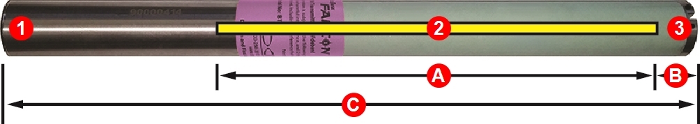
- Battery cap
- Slot position
- Front end cap
A. Slot length
B. Slot position
C. Transmitter length
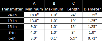
While an Ares transmitter is compatible with older housing slot dimensions, optimal performance requires the A and B measurements shown above.
DigiTrak SuperCell-R battery and charger directions and technical specifications
Product IDs/Model numbers:
DLiChKit2.5 - DigiTrak Li charger kit 2.5a includes:
- CrSRD/RBC1 Cradle for SR40-R SuperCell-R - 1 of 2
- Ch2cLi/M3546 Charger for SR40 SuperCell-R 2.5A - 2 of 2
- SR40-R/RBP2v1 SuperCell-R Li-Ion rechargeable battery
Description: The DigiTrak Lithium-Ion charger kits include an AC power cord, a charger, a battery cradle, and two Lithium-Ion rechargeable batteries.
These batteries are for the exclusive use of the DigiTrak SuperCore transmitters. They can be recharged up to 300 times. The SR40-R SuperCell-R battery cannot be used in other DCI transmitters.
The battery charger operates from an AC power (100-240Vac, 50-60Hz, max. 0.74 max.). The AC power cord shipped with your system is standard to your region.
Safety warnings
- The charger is intended for indoor use and is not waterproof or dustproof. To avoid overheating, make sure there is sufficient air circulation around the charger when in use. Do not cover it up.
- The charger must be kept from heat sources and may not be used in environments with flammable or explosive atmospheres.
- The charger is only intended for use with DigiTrak SuperCell-R batteries. Do not use it with other types of batteries.
- Only use the cords that come with the charger.
- Unplug the charger when not in use.
- The charger contains hazardous voltages, and there are no user-replaceable parts inside. Never attempt to remove the cover. Contact DCI Support.
- Do not dispose of the charger with municipal waste. See the article "Equipment and Battery Disposal" in the Safety chapter.
Setup and charging
- Connect the AC power cord to the charger and plug it into an AC outlet. If needed, you can connect the charger plug to the cradle. The charger may take up to 15 seconds to initialize. The LED indicator will flash green, indicating that the charger is ready.
- First, insert the end of the battery with the contacts into the cradle and press the battery firmly into it.
- The LED indicator shows the charging stage and errors.
- yellow (solid) - first 80% charging, approximately 2 hours.
- yellow (blinking) - last 20% to full charge. The battery can be used at 80% charge,
- green (solid) - fully charged, approximately 4 hours total.
- Remove the battery and unplug the charger.
- If you leave the battery in the charger, it will occasionally flash yellow as the charger tops the battery off to keep it fully charged. Do not leave the battery in the charger for more than 24 hours.
- If you are charging multiple batteries in a row, wait 15 seconds before inserting another battery.
LED indicators
- Yellow (solid and blinking): battery charging
- Yellow with 1 red blink: battery temperature is too low (<32°F/0°C)
- Yellow with 2 red blinks: battery temperature is too high (>113°F /45°C)
- Green (solid): charge complete
- Green (blinking): no battery detected
- Red 2 blinks: the battery is connected to the charger with the wrong polarity
- Red 3 blinks: charger output is shorted. Check the output cable connection
- Red 4 blinks: battery voltage is low. Check battery status or voltage
- Red 5 blinks: The safety timer has run out. Check battery status or capacity
- LED off: Battery voltage is too high. Check the battery voltage
Battery Life
Battery life is determined by the locator that the transmitter is paired with and the selected power mode. See the transmitter specification article for that model for details.
Specifications
- Charger weight (without battery or cables): 11.46 oz (325g)
- Charger power input rating: - 100-240Vac, 50-60Hz, max. 0.74 max.
- Charger power output rating: 21W max output power (8.4VDC at 2.5A)
- Li 2.5A battery weight and dimensions: 6.2 oz/.37 in X 2.48" (176 g/.94 cm X 6.3 cm)
Operating Environment
- Battery operation: 32°F to 113°F (0°C to 45°C)
Storage: -13°F to 140°F (-25°C to 60°C)
Warning: The battery will shut off at greater than 185°F (85°C) and the temperature dot on the battery will turn black. - Humidity 15 - 93% RH NC
- Atmospheric pressure 70 - 106 kPa (700 - 1060 hPa)
Warranty: Charger for one year and battery for 90 days from the date of purchase. The warranty will be canceled if the battery temperature rises above 185°F (85°C) and the temperature dot on the battery turns black.
COMPLIANCE RATINGS
This equipment complies with the following: Part 15 of the Rules of the FCC; Industry Canada license-exempt RSS standards; ACMA Radio Communications (Short Range Devices) Standard (2014). Operation is subject to the following two conditions: (1) this equipment may not cause harmful interference, and 2) this equipment must accept any interference received, including interference that may cause undesired operation.
Before You Start
You can download software updates with new features and upgrades for your DigiTrak Ares locator over Wi-Fi, including stable mobile hotspots. The locator automatically disconnects from Wi-Fi after the update is complete.
For more information about connecting to Wi-Fi on your locator, see the article Connect to Wi-Fi.
Some software updates are optional. However, some features and functionality will not be available without the current software. If a software update is available, a message is displayed on the equipment page on the myDCI portal. You can also check for updates in Settings.
From the Home screen, scroll down and select Settings.
On the Settings page, under System, select Software updates.
Select the network to use and then enter the password using the D-pad and trigger. The locator will remember the password the next time you connect.
If a Wi-Fi network is hidden and doesn't broadcast their SSID, you can still connect to these networks if you know: 1) the network name or SSID 2) the type of encryption used by the network 3) the network password.
After connecting, the locator checks for updates.
- If the locator software is up-to-date, the current version is displayed, with a message. Select Close to return to the Settings menu.
- If the locator software needs an update, click Download and Install, and then select Begin update. When the update is complete, the locator will restart.
- If the update fails, contact DCI Customer Support.
Do not turn off the locator or switch screens until the update is complete. Time to update will vary depending on connection speed and may take several minutes. Make sure the locator battery is at least half full, so that the update is not interrupted.
Indicates the presence of interference (attenuation *). If the icon is red or surrounded by a red box, this is excessive attenuation, which can make depth readings inaccurate.
Bluetooth is active, but not connected to a transmitter or device.
Bluetooth error
Bluetooth attempting to connect to transmitter.
Bluetooth paired with a transmitter
Bluetooth is attempting to connect to smart device
Bluetooth is successfully connected to smart device
Indicates that Max Mode is enabled to stabilize roll/pitch data and depth readings when drilling at the transmitter’s range limit due to extreme depth or interference, which will vary by jobsite.
Select to access more settings and details.
Locator battery charge level. The icon changes to yellow when the battery is lower than 39% and red when lower than 20%.
Power mode selected for the transmitter (1 bar=low, 2 bars=standard, 3 bars=high)
Indicates the transmitter band is assigned an ultra-low band (0.3, 0.5, or 0.7) for use in areas of high passive interference, such as rebar.
Transmitter battery charge level. The icon changes to yellow when the battery is lower than 39% and red when lower than 20%.
Telemetry active. The locator is sending a signal to a remote over telemetry channel 1.
Telemetry channel off - no signal is being sent to remote display.
Telemetry paused - no signal is being set to remote
Wi-Fi connected at 100%
Wi-Fi attempting to connect
Wi-Fi error
Il localizzatore attenua automaticamente il segnale del trasmettitore quando si effettua la localizzazione a profondità ridotte per ridurre l'eccessiva intensità del segnale. L'attenuazione è attiva ogni volta che appare una A sullo schermo della Modalità Localizzazione. L'attenuazione può anche indicare la presenza di interferenze eccessive, che possono rendere inaccurate le letture della profondità.
L'attenuazione è normale quando il localizzatore è vicino al trasmettitore; l'attenuazione durante la calibrazione è un avviso a spostarsi e calibrare in un'area con meno interferenze. Il localizzatore non si calibrerà quando la forza del segnale lampeggia, il che indica la presenza di interferenze estreme.
Depth Increase in Inches (cm)
| % slope | Depth increase cm | % slope | Depth increase cm |
|---|---|---|---|
| 1 | 2 | 14 | 43 |
| 2 | 5 | 15 | 46 |
| 3 | 10 | 16 | 48 |
| 4 | 13 | 17 | 51 |
| 5 | 15 | 18 | 53 |
| 6 | 18 | 19 | 56 |
| 7 | 20 | 20 | 61 |
| 8 | 25 | 21 | 64 |
| 9 | 28 | 22 | 66 |
| 10 | 30 | 23 | 69 |
| 11 | 33 | 24 | 71 |
| 12 | 36 | 25 | 74 |
| 13 | 36 | 26 | 76 |
| % slope | Depth increase cm | % slope | Depth increase cm |
|---|---|---|---|
| 27 | 79 | 41 | 117 |
| 28 | 81 | 42 | 117 |
| 29 | 84 | 43 | 119 |
| 30 | 86 | 44 | 122 |
| 31 | 91 | 45 | 124 |
| 32 | 94 | 46 | 127 |
| 33 | 97 | 47 | 130 |
| 34 | 99 | 50 | 137 |
| 35 | 102 | 55 | 147 |
| 36 | 104 | 60 | 157 |
| 37 | 107 | 70 | 175 |
| 38 | 109 | 80 | 191 |
| 39 | 112 | 90 | 203 |
| 40 | 114 | 100 | 216 |
Slopes between 50% and 100% are provided for reference only and do not represent typical drilling conditions. All numbers are based on math only and do not take into account extremely soft or extremely hard soil conditions, which may cause depth values to vary.
Depth Increase in Inches (cm)
| % slope | Depth increase cm | % slope | Depth increase cm | % slope | Depth increase cm |
|---|---|---|---|---|---|
| 1 | 2 | 19 | 56 | 37 | 107 |
| 2 | 5 | 20 | 61 | 38 | 109 |
| 3 | 10 | 21 | 64 | 39 | 112 |
| 4 | 13 | 22 | 66 | 40 | 114 |
| 5 | 15 | 23 | 69 | 41 | 117 |
| 6 | 18 | 24 | 71 | 42 | 117 |
| 7 | 20 | 25 | 74 | 43 | 119 |
| 8 | 25 | 26 | 76 | 44 | 122 |
| 9 | 28 | 27 | 79 | 45 | 124 |
| 10 | 30 | 28 | 81 | 46 | 127 |
| 11 | 33 | 29 | 84 | 47 | 130 |
| 12 | 36 | 30 | 86 | 50 | 137 |
| 13 | 36 | 31 | 91 | 55 | 147 |
| 14 | 43 | 32 | 94 | 60 | 157 |
| 15 | 46 | 33 | 97 | 70 | 175 |
| 16 | 48 | 34 | 99 | 80 | 191 |
| 17 | 51 | 35 | 102 | 90 | 203 |
| 18 | 53 | 36 | 104 | 100 | 216 |
Slopes between 50% and 100% are provided for reference only and do not represent typical drilling conditions. All numbers are based on math only and do not take into account extremely soft or extremely hard soil conditions, which may cause depth values to vary.
Depth Increase in Inches (cm)
| % slope | Depth increase cm | % slope | Depth increase cm | % slope | Depth increase cm |
|---|---|---|---|---|---|
| 1 | 5 | 19 | 86 | 37 | 157 |
| 2 | 10 | 20 | 89 | 38 | 163 |
| 3 | 13 | 21 | 94 | 39 | 165 |
| 4 | 18 | 22 | 99 | 40 | 170 |
| 5 | 23 | 23 | 102 | 41 | 173 |
| 6 | 28 | 24 | 107 | 42 | 178 |
| 7 | 33 | 25 | 112 | 43 | 180 |
| 8 | 36 | 26 | 114 | 44 | 183 |
| 9 | 41 | 27 | 19 | 45 | 188 |
| 10 | 46 | 28 | 124 | 46 | 191 |
| 11 | 51 | 29 | 127 | 47 | 196 |
| 12 | 53 | 30 | 132 | 50 | 203 |
| 13 | 58 | 31 | 135 | 55 | 221 |
| 14 | 64 | 32 | 140 | 60 | 236 |
| 15 | 69 | 33 | 142 | 70 | 262 |
| 16 | 71 | 34 | 147 | 80 | 284 |
| 17 | 76 | 35 | 150 | 90 | 305 |
| 18 | 81 | 36 | 155 | 100 | 323 |
Slopes between 50% and 100% are provided for reference only and do not represent typical drilling conditions. All numbers are based on math only and do not take into account extremely soft or extremely hard soil conditions, which may cause depth values to vary.
FCC Compliance Statement
This device complies with part 15 of the FCC Rules. Operation is subject to the following two conditions: (1) This device might not cause harmful interference, and (2) this device must accept any interference received, including interference that might cause undesired operation.
DCI is responsible for FCC compliance in the United States. Changes or modifications to any DCI equipment not expressly approved and carried out by DCI will void the user's Limited Warranty and the FCC's authorization to operate the equipment.
| The RTP Transmitter contains the following: Laird Bluetooth 5.1 Data Module, Model BL653 FCC 1D SQGBL653 1 ISED 1D 3147A-BL653 For manufacture's module certifications, visit https://www.ezurio.com/ |
ISED Canada Compliance Statement
This device complies with Innovation, Science and Economic Development Canada's license-exempt RSS. Operation is subject to the following two conditions:
1. This device may not cause interference.
2. This device must accept any interference, including interference that may cause undesired operation of the device.
CAN ICES-3 (A)/NMB-3(A)
DigiTrak Locators are classified as Class 2 radio equipment per the Radio Equipment
Directive 2014/53/EU and may not be legal to operate or may require a user license to operate in some countries. For a list of restrictions, please send a request to productcompliance@digital-control.com.
Déclaration de conformité FCC
Cet appareil est conforme à la partie 15 des règles FCC. Son fonctionnement est soumis aux deux conditions suivantes : (1) cet appareil ne doit pas causer d'interférences nuisibles, et (2) cet appareil doit accepter toute interférence reçue, y compris les interférences pouvant entraîner un fonctionnement indésirable.
DCI est responsable de la conformité FCC aux États-Unis. Toute modification apportée à un équipement DCI qui n'a pas été expressément approuvée et effectuée par DCI annulera la garantie limitée de l'utilisateur et l'autorisation de la FCC d'utiliser l'équipement.
| L'émetteur RTP contient les éléments suivants : Module de données Bluetooth 5.1 Laird, modèle BL653 FCC 1D SQGBL653 1 ISED 1D 3147A-BL653 Pour obtenir les certifications des modules du fabricant, consultez le site https://www.ezurio.com/. |
Déclaration de conformité ISED Canada
Cet appareil est conforme aux RSS exemptés de licence d'Innovation, Sciences et Développement économique Canada. Son fonctionnement est soumis aux deux conditions suivantes :
1. Cet appareil ne doit pas causer d'interférences.
2. Cet appareil doit accepter toute interférence, y compris les interférences pouvant entraîner un fonctionnement indésirable de l'appareil.
CAN ICES-3 (A)/NMB-3(A)
Les localisateurs DigiTrak sont classés comme des équipements radio de classe 2 conformément à la directive 2014/53/UE relative aux équipements radio
et leur utilisation peut être illégale ou nécessiter une licence d'utilisation dans certains pays. Pour obtenir la liste des restrictions, veuillez envoyer une demande à productcompliance@digital-control.com.
DigiTrak Locators are classified as Class 2 radio equipment per the Radio Equipment
Directive 2014/53/EU and may not be legal to operate or may require a user license to operate in some countries. For a list of restrictions, please send a request to productcompliance@digital-control.com.
Les localisateurs DigiTrak sont classés comme équipements radio de classe 2 conformément à la directive 2014/53/UE relative aux équipements radio
et leur utilisation peut être illégale ou nécessiter une licence d'utilisation dans certains pays. Pour obtenir la liste des restrictions, veuillez envoyer une demande à productcompliance@digital-control.com.

This device meets the requirements outlined in Radiocommunications (Short Range Devices) Standard 2014.

Cet appareil est conforme aux exigences énoncées dans la norme 2014 sur les radiocommunications (appareils à courte portée).
This portable device has been shown to be compliant for localized specific absorption rate (SAR) for uncontrolled environment/general exposure limits specified in ANSI/IEEE Std. C95.1-1992 (FCC 47 CFR § 2.1093) and IC Safety Code 6 (RSS-102).
| Country | Allowed Frequencies (MHz) | Limitations | Region (legacy) | Region (new) |
|---|---|---|---|---|
| Austria | 458.6, 458.65, 458.7, and 458.75 | Yes* | UK | GB |
| Belgium | 458.6, 458.65, 458.7, and 458.75 | Yes* | UK | GB |
| Bulgaria | 458.6, 458.65, 458.7, and 458.75 | Yes* | UK | GB |
| Croatia | 458.6, 458.65, 458.7, and 458.75 | UK | GB | |
| Cyprus | 458.6, 458.65, 458.7, and 458.75 | UK | GB | |
| Czech Republic | 449.8, 449.85, 449.9, 449.95 | UK | GB | |
| Denmark | 458.6, 458.65, 458.7, and 458.75 | UK | GB | |
| Estonia | 449.8, 449.85, 449.9, and 449.95 | Yes* | ES | ES |
| Finland | 458.6, 458.65,458.7, and 458.75 | UK | GB | |
| France | 458.6, 458.65, 458.7, and 458.75 | UK | GB | |
| Germany | 458.6, 458.65, 458.7, and 458.75 | UK | GB | |
| Greece | 458.6, 458.65, 458.7, and 458.75 | UK | GB | |
| Hungary | 433.65 and 433.70 | Yes* | SW or SU | CH |
| Iceland | 458.6, 458.65, 458.7, and 458.75 | UK | GB |
| Country | Allowed Frequency (MHz) | Limitations | Region (legacy) | Region (new) |
|---|---|---|---|---|
| Ireland | 458.6, 458.65, 458.7, and 458.75 | UK | GB | |
| Italy | 458.6, 458.65, 458.7, and 458.75 | Yes* | UK | GB |
| Latvia | 449.8, 449.85, 449.9, 449.95 | Yes* | UK | GB |
| Liechtenstein | 433.65 and 433.70 | SW or SU | CH | |
| Lithuania | 449.8, 449.85, 449.9, 449.95 | Yes* | UK | GB |
| Luxembourg | 458.6, 458.65, 458.7, and 458.75 | Yes* | UK | GB |
| Malta | 458.6, 458.65, 458.7, and 458.75 | Yes* | UK | GB |
| Netherlands | 451.03 and 451.09 | Yes* | NL | NL |
| Norway | 458.6, 458.65, 458.7, and 458.75 | UK | GB | |
| Poland | 458.6, 458.65, 458.7, and 458.75 | UK | GB | |
| Portugal | 458.1125, 458.125, 458.1375, 458.15 | PT | ||
| Romania | 433.65 and 433.70 | UK | CH | |
| Slovak Republic | 458.6, 458.65, 458.7, and 458.75 | UK | GB | |
| Slovenia | 449.8, 449.85, 449.9, 449.95 | Yes* | UK | GB |
| Spain | 449.8, 449.85, 449.9, and 449.95 | ES | ES | |
| Sweden | 458.6, 458.65, 458.7, and 458.75 | UK | GB | |
| Switzerland | 433.65 and 433.70 | SW or SU | CH |
*Individual user license required–check with your local authority. Unless otherwise noted, the maximum radiated power output is limited to 100m WERP. Please contact DCI at productcompliance@digital-control.com, if additional technical information or translation is required.
The FAR5 contains a BLE Radio with the following specifications: Frequency Bands: 2402-2480 mHz Transmit Power: 0.00135 W EIRP
The AEO2 contains WiFi/BT and Cellular/GPS radios which operate on the following bands:
CE BANDS
GSM900: 880.2 – 914.8 MHz GSM1800: 1710.2 – 1784.8MHz
LTE Band 1: 1920 – 1980 MHz
LTE Band 3: 1710 – 1785 MHz
LTE Band 5: 824 – 849 MHz
LTE Band 7: 2500 – 2570 MHz
LTE Band 8: 880 – 915 MHz
LTE Band 20: 832 – 862 MHz
LTE Band 28: 703 – 748 MHz
LTE Band 38: 2570 – 2620 MHz
LTE Band 40: 2300 – 2400 MHz
LTE Band 41: 2496 – 2690 MHz
COMPLIANCE RATINGS
This equipment complies with the following: Part 15 of the Rules of the FCC; Industry Canada license-exempt RSS standards; ACMA Radio Communications (Short Range Devices) Standard (2014). Operation is subject to the following two conditions: (1) this equipment may not cause harmful interference, and 2) this equipment must accept any interference received, including interference that may cause undesired operation.
Contact
DCI USA
19625 62nd Ave S, Suite B103
Kent, WA USA 98032
DCI@digital-control.com
1.800.288.3610
1.425.251.0559
DCI Australia
2/9 Frinton Street Southport
Queensland 4215 Australia
DCI.Australia@digital-control.com
+61.7.5531.4283
+61.7.5531.2617
DCI China
368 Xingle Road Huacao Town
Minhang District Shanghai 201107, P.R.C
DCI.China@digital-control.com
+86.400.100.8708
+86.21.6432.5186
DCI Europe
Brueckenstraße 2
97828 Marktheidenfeld Germany
DCI.Europe@digital-control.com
+49.9391.810.6100
+49.9391.810.6109
DCI India
Unit No. 1022, 10th Floor DLF Tower B Jasola District Center
New Delhi 110025 India
DCI.India@digital-control.com
+91.11.4507.0444
+91.11.4507.0440
DCI Philippines
404-405 Energy Opt. Bldg Prime St, Madrigal Business Park 2
Alabang Muntinlupa City, Philippines 1780
DCI.Philippines@digital-control.com
(02)79802647
+632-79802647